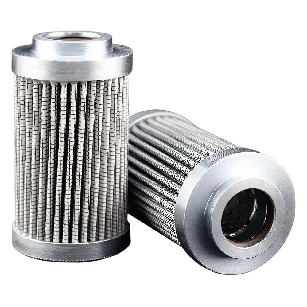
Industrial Sensors for Power Plants: What to Demand from Suppliers
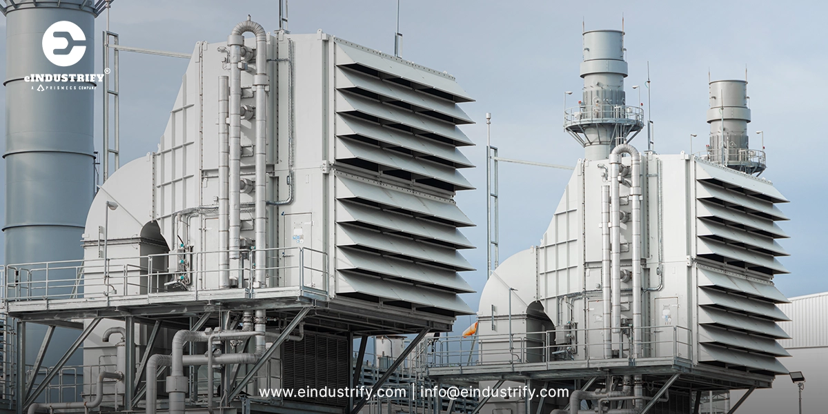
Industrial sensors in power plants are not commodity purchasesA replacement pressure transmitter arrives two days before a turbine restarts, but the supplier cannot confirm the output signal, hazardous-area approval, or calibration traceability. The part looks close enough on the datasheet, yet the controls engineer will not release it for installation because the loop cannot be validated.That is the real buying environment for industrial sensors in power plants. The purchase is not just a part number transaction. It affects starts, trips, derates, safety loops, emissions compliance, maintenance planning and outage duration.Generic sensor selection advice rarely helps procurement teams in that situation. Power-plant buyers need to know what to demand from suppliers before a sensor reaches receiving inspection, not after the maintenance team opens the box.Why power-plant sensor buying is different from general industrial sensor buyingThe buying risk is in the loop, not the deviceIndustrial sensors used in factory automation often support counting, positioning, packaging, or machine guarding. Those applications matter, but the procurement risk profile is different. In a power plant, a pressure transmitter, vibration probe, RTD, thermocouple, flow meter, gas detector, or level transmitter can sit inside a control loop that protects availability.A wrong sensor range creates nuisance alarms. A slow response time affects trip logic. A missing hazardous-area certificate blocks installation near fuel gas equipment. A substitute with the wrong output signal turns a simple MRO purchase into a controls rework request.What procurement must verify before price comparisonPower generation exposes instrumentation to conditions that many catalog pages treat as secondary details. Turbine compartments, generator skids, cooling systems, lube oil systems, transformers and outdoor balance-of-plant areas expose sensors to heat, vibration, moisture, electrical noise, corrosive atmospheres and limited maintenance access.Procurement teams also work under schedule pressure. During an outage, a sensor is not simply backordered. It is a schedule risk. Every missing certificate, unclear cross-reference or unsupported alternate consumes engineering review time that the outage plan did not reserve.The practical question is not only whether the industrial sensor measures the right variable. The better question is whether the supplier can prove the sensor fits the asset, loop, environment, documentation package, and delivery window.Map sensor requirements to the power-plant asset before evaluating suppliersPower-plant sensor procurement should start with the asset, not the sensor family. A pressure sensor on a fuel gas skid, a differential pressure transmitter across an air filter and a cooling water pressure transmitter all measure pressure. They do not carry the same installation risk, documentation burden, or failure consequence.Asset mapping forces procurement and engineering teams to define the service before requesting a quote. The RFQ should identify the equipment package, tag number, process media, normal operating range, alarm or trip function, required output, environmental exposure, and existing control-system interface.This matters because suppliers often quote from a product category, while plants buy a loop. A part that satisfies the measurement range still fails the application if the process of connection, response time, enclosure rating, hazardous-area approval or calibration data does not match the installed requirement.Asset-level mapping prevents procurement from treating every pressure, flow or temperature sensor as interchangeable.Gas turbine and steam turbine sensor requirementsGas turbine and steam turbine sensor requirements start with reliability under heat, vibration and fast transient conditions. Turbine packages use sensors for bearing temperature, vibration, exhaust temperature, speed, lube oil pressure, fuel gas pressure, enclosure temperature, inlet conditions and start permissive.For LM2500, LM6000, heavy-duty gas turbines and steam turbine trains, procurement should demand more than a matching part number. Suppliers should confirm measurement range, response time, probe length, mounting interface, cable specification, connector type, shielding and compatibility with the installed monitoring or control system.A substitute vibration probe or speed sensor that physically fits the mounting location still needs verification against the existing monitor, extension cable, calibration standard and trip logic. Equivalent is not acceptable unless the supplier proves form, fit, function, and signal behavior.Generator, transformer, and electrical-system sensor requirementsGenerator and transformer sensors introduce different sets of requirements. Winding temperature, bearing vibration, generator ventilation, current sensing, voltage sensing, transformer oil temperature, oil level, dissolved gas monitoring and excitation feedback all support electrical reliability.The supplier must confirm electrical compatibility, insulation environment, enclosure rating, grounding requirements, and output signal. In areas near generator switchgear or excitation equipment, electromagnetic compatibility is not optional. Sensor electronics and signal wiring must tolerate switching transients, ground potential differences and electrical noise.For digitally integrated electrical assets, procurement should also ask for communication details. A device that advertises Modbus, HART or Ethernet support still needs to register maps, configuration files, firmware details and commissioning instructions.Balance-of-plant, cooling, fuel, lube oil, and environmental systemsBalance-of-plant equipment creates many sensor purchases that delay maintenance work. Cooling water flow transmitters, lube oil temperature sensors, fuel gas pressure switches, differential pressure transmitters, level sensors, air intake filtration sensors, humidity sensors, gas detectors and emissions-related instruments all sit outside the turbine core but still affect availability.These applications often combine ordinary measurements with difficult conditions. A cooling water sensor faces moisture and corrosion. A lube oil skid sensor faces vibration, heat, and contamination. A fuel gas sensor or gas detector enters hazardous-area review.Procurement should not let those sensors move through a generic buying path. The asset service should decide the documentation package, inspection requirement, spare strategy, and supplier response expectation.Demand operating-environment proof, not just a datasheet claimA datasheet operating range is a starting point, not proof of field suitability. Power-plant buyers should demand evidence that the sensor survives the actual installation environment, including ambient temperature, process temperature, humidity, ingress exposure, vibration, shock, corrosion, dust, washdown and electromagnetic disturbance.IEC 60529 defines IP ratings for enclosure protection against dust and liquids. That rating does not replace installation reviews. A device rated for liquid ingress still needs proper glands, cable entries, mounting orientation and installation discipline. NEMA enclosure types add another layer for North American projects, especially where corrosion, oil, coolant or outdoor exposure is part of the service.Power plants expose sensors to conditions that rarely appear together in basic automation examples. A sensor mounted on a turbine skid can face elevated ambient temperature, vibration, oil mist and restricted access. A sensor near the generator switchgear can face surge, electrical noise, and grounding issues.Environmental evidence suppliers should provideSuppliers should provide datasheets showing rated operating temperature, storage temperature, process temperature limits, ingress protection, enclosure material, cable or connector rating, vibration and shock limits and corrosion-resistance information. The buyer should request the actual certificate or test basis when the rating is critical.For outdoor or washdown areas, ask how the rating was achieved. The answer should identify the enclosure, cable gland, connector, and installation requirements. An IP67 sensor body connected through an unapproved cable entry does not deliver an IP67 installation.For turbine compartments, cooling skids, fuel systems, and coastal sites, ask for material compatibility. Stainless steel, coated aluminum, polymer housings, elastomers and connector materials age differently under heat, salt, chemicals, oil and UV exposure.Application conditions that change sensor selectionThe same measurement variable changes specification when the installation moves from a clean panel to a plant asset. A pressure transmitter in a dry instrument rack is not the same procurement decision as a pressure transmitter on a vibrating fuel skid.Wet areas push the review toward ingress protection, cable sealing, drainage, and corrosion resistance. High-vibration skids require mounting integrity, connector retention, and vibration rating. Outdoor substations require temperature range, UV resistance, grounding, surge protection and enclosure suitability.Turbine enclosures and acoustic packages add serviceability concerns. A sensor that requires frequent calibration or difficult access should be reviewed against outage intervals and maintenance windows, not only purchase price.Demand measurement performance and calibration evidenceSensor performance claims must be tied to the plant control needs. Accuracy, repeatability, resolution, response time, drift, hysteresis, and measurement range do not carry equal weight in every loop. A cooling water trend sensor, a permissive switch and a trip-related transmitter require different scrutiny.Calibration evidence matters because a sensor is only useful if the plant can trust the measurement. A supplier should identify the calibration method, test points, tolerance, reference standard, calibration date, serial number and measurement uncertainty where applicable.For accredited calibration, ISO/IEC 17025 is the recognized laboratory competence standard for testing and calibration laboratories. NIST describes metrological traceability as an unbroken chain of calibrations to specified reference measurement standards. Both concepts belong in critical sensor procurement files when measurement confidence drives plant decisions.Minimum calibration documents to requestFor critical industrial sensors, request a calibration certificate that identifies the sensor's serial number, calibration date, calibration procedure, reference standard, test points, measured results, tolerance, uncertainty, and calibration status. The certificate should match the device being shipped, not a generic production batch.For pressure, temperature, flow, and vibration instruments, ask for as-found and as-left data when the device is repaired or recalibrated. This helps maintenance teams understand drift and decide whether the instrument should remain in the same service.Procurement should also request the recommended calibration interval and field calibration instructions. A sensor that needs calibration equipment the plant does not own creates a hidden maintenance cost.Performance questions suppliers should answer before approvalThe supplier should answer specific performance questions before the purchase order is released. What is the calibrated range? What is the maximum process pressure or temperature? What is the response time? What is the long-term drift? What happens if the sensor exceeds its overpressure or temperature limit?Ask how the sensor behaves at the edges of the measurement range. A device that performs well at mid-scale can still be unsuitable near alarm or trip setpoints.For replacement sensors, ask whether the quoted range, output scaling and damping match the installed loop. A mismatch forces controls changes, field recalibration or alarm rationalization work during a maintenance window.Demand control-system and signal compatibility before purchaseControl-system compatibility should be confirmed before sourcing, not during commissioning. Power plants still use a mix of DCS, SCADA, PLC, relay panels, turbine control systems, vibration monitors, and standalone skid controllers. Industrial sensors must fit that installed architecture.The basic output signal is only the first checkpoint. Procurement should confirm 4-20 mA, 0-10 V, relay output, RTD, thermocouple, pulse, frequency, HART, Modbus, Profibus, Profinet, OPC-UA, IO-Link or Ethernet communication as required by the loop. The supplier should also confirm input card compatibility, power requirements, wiring method, grounding, and shield termination.A common outage problem starts with a physically correct sensor that has the wrong electrical personality. The maintenance team receives a replacement transmitter with the right process connection and range, but the output is 0-10 V instead of loop-powered 4-20 mA. The part is not defective, but it does not belong in that loop.Supplier proof for DCS, PLC, and SCADA integrationThe supplier should provide wiring diagrams, loop-power requirements, signal scaling, communication protocol details, configuration files, and commissioning instructions. For digital devices, the buyer should request to register maps, device description files, firmware version and diagnostic data availability.For PLC and DCS integrations, confirm the input card type before quoting. Two-wire loop-powered transmitters, four-wire devices, dry contacts, NAMUR sensors, RTDs, thermocouples, and pulse outputs create different wiring and configuration requirements.Procurement should also ask who supports commissioning questions. If the supplier cannot answer wiring, scaling, and configuration questions, the plant absorbs that burden during installation.Why protocol support alone is not enoughProtocol support is not the same as usable integration. A device that says Modbus still needs the register map, baud rate, parity, addressing, data type, scaling and exception behavior. A HART device still needs device description support and loop access.Firmware matters as much as the protocol label. Plants with validated configurations should know whether the supplier is shipping the same firmware revision or an updated version. An undocumented revision change can affect diagnostics, scaling or configuration tools.Cybersecurity also enters the review for networked devices. Ethernet-connected sensors and gateways should be evaluated against the plant network architecture, access controls, patching process, and vendor support model.Demand certifications, compliance, and hazardous-area documentationCertifications should match the installed location, not the supplier's default catalog offering. Power plants contain ordinary locations, wet areas, outdoor areas, battery rooms, fuel gas areas, turbine compartments, chemical storage areas, and electrical rooms. Each location changes the compliance question.For hazardous areas, procurement should request the actual certificate, not only a catalog mark. ATEX Directive 2014/34/EU covers equipment and protective systems intended for use in potentially explosive atmospheres. OSHA 1910.307 covers electrical equipment and wiring in hazardous classified locations in U.S. workplaces.Safety-related loops need a separate review. IEC 61508 addresses functional safety for electrical, electronic and programmable electronic safety-related systems. A sensor used in a safety function should be evaluated as part of that safety lifecycle, not as a standalone commodity.Hazardous-area and safety-related applicationsFuel gas skids, turbine enclosures, gas detection points, hydrogen systems, chemical feed areas and battery rooms require location-specific review. The supplier should confirm whether the sensor is intrinsically safe, explosion-proof, non-incentive, or suitable for the classified area defined by the plant.For safety instrumented functions, the buyer should ask for the safety manual, SIL capability information, proof test interval, failure rates, diagnostic coverage, and restrictions on use. A generic transmitter installed inside a safety loop does not become safety-rated because it measures the right variable.The plant engineering authority should verify that barriers, isolators, wiring methods, and installation practices match the certified protection concept. Procurement should never treat the device certificate as a whole safety case.Compliance documents procurement should requestRequest the certificate of compliance, declaration of conformity, hazardous-area certificate, safety manual, installation manual, material certificate where applicable and factory test report. For safety-related sensors, ask for SIL documentation and proof-test guidance.The document package should identify the exact model, option codes, firmware revision, enclosure, connection type, and approval markings. A certificate for a related model of family is not enough unless the quoted configuration is clearly covered.Procurement should also confirm country or regional acceptability. ATEX, IECEx, UL, CSA and local electrical code requirements are not interchangeable by default.Demand reliability, failure-mode, and lifecycle informationReliability questions should come before price comparison. In a power plant, sensor failure rarely stays inside the instrument. It travels into alarms, permissives, trips, maintenance decisions, outage planning and operator confidence.A failed temperature sensor can block a start permissive. A drifting pressure transmitter can create false low-pressure alarms. A vibration probe with intermittent signal loss can generate nuisance turbine trips. A level sensor with poor repeatability can cause unnecessary pump cycling or missed inventory warnings.Suppliers should provide lifecycle information, not just availability on the day of quote. Ask for service life, warranty history, installed base, failure history, recommended maintenance, spare availability, repair options and obsolescence status.Failure consequences suppliers rarely disclose unless askedSuppliers often describe what the sensor measures. Procurement should also ask what happens when it fails. Does it fail high, fail low, freeze the last value, generate a fault output or disappear from the network?Those details matter during plant operation. A false high temperature signal can derate or trip equipment. A false low-pressure signal can block startup. A missed gas detection alarm creates safety exposure. A bad vibration signal forces operators to choose between protecting equipment and maintaining dispatch.Ask the supplier to describe diagnostics, fault indication, failure behavior, and recommended maintenance response. That answer should be documented before the sensor becomes a critical spare.Reliability questions to include in supplier evaluationAsk MTBF data if available, but do not stop there. Request the installed base, service history, warranty process, common failure modes, maintenance interval, and expected lifecycle status. A supplier with no service history for the application should not be treated like an approved source for critical loops.Ask whether the device is active, mature, restricted, last-time-buy or obsolete. Lifecycle status changes the stocking decision.Also ask how the supplier handles warranty replacements during outages. A warranty of credit after a forced outage does not recover lost generation or restart time.Demand replacement equivalency and obsolescence supportReplacement sensor sourcing is where many industrial buyers lose time. The original part is obsolete, the OEM package documentation is incomplete, or the installed sensor has a superseded model number. A supplier then offers an equivalent part without proving equivalency at the loop level.Equivalency must cover form, fit, function, approvals, signal behavior and documentation. Form means physical dimensions, mounting, process connection, connector and cable routing. Fit means the device can be installed without mechanical or electrical modification. Function means it performs the same measurement role with acceptable accuracy, response, output, diagnostics, and environmental suitability.Obsolescence support should include cross-reference discipline. A capable supplier can explain why the alternate is acceptable, what changed, and which plant conditions still require engineering approval.What suppliers must prove before offering an alternateSuppliers must prove the same measurement range, output signal, process connection, enclosure rating, approvals, wiring method, response time, calibration basis, and environmental rating. They should also identify every difference between the original and proposed alternate.The alternate should come with a datasheet, certificate package, wiring diagram, calibration document, and cross-reference statement. If the supplier cannot explain the difference between replacement, equivalent, and recommended substitute, the buyer should escalate the review.For high-risk loops, require engineering approval before purchasing. Procurement should not accept a substitute solely because it fits the thread and appears in stock.When a cheaper substitute creates plant riskA cheaper substitute creates risk when the saving comes from missing documentation, unclear origin, incomplete approvals, weak calibration evidence or unsupported compatibility. Counterfeit and gray-market sensors create the same problem: the plant cannot verify what it is installing.A low-cost sensor is not a low-cost decision if it causes a failed start, commissioning delay or trip investigation. For critical applications, authenticity, traceability and supplier accountability matter as much as unit price.The right comparison is total procurement risk, not line-item cost.Demand availability, lead-time, and critical-spares supportAvailability is a technical issue when the sensor protects a critical asset. A sensor with perfect specifications and a 16-week lead time does not help a plant facing a forced outage, hot-gas-path inspection, data center generator test or urgent restart.Critical-spares planning should identify which sensors deserve stock review before failure. Prioritize instruments tied to startup permissives, turbine protection, generator availability, lube oil systems, fuel systems, cooling systems, emissions compliance and safety alarms.Procurement should ask suppliers for current stock, production lead time, minimum order quantity, expedited options, replacement availability and documentation turnaround. The supplier's ability to ship the part is only one part of readiness. The ability to ship the correct documents matters just as much.Sensor spares that deserve critical-spares reviewPower plants should review spares for vibration probes, speed sensors, pressure transmitters, differential pressure transmitters, RTDs, thermocouples, level transmitters, gas detectors, flow meters, temperature switches, pressure switches and generator monitoring sensors.The review should consider asset criticality, failure history, supplier lead time, installed base, interchangeability and documentation requirements. A common sensor used across multiple skids deserves different stocking logic than a one-off legacy device.For high-consequence loops, stock the sensor with the required certificate package, not just the hardware.Supplier commitments to demand before an outageBefore an outage, ask suppliers to confirm lead time, stock status, quote validity, documentation availability, warranty handling, emergency support, and approved alternates. The confirmation should be written into the procurement file.Ask whether the quoted sensor ships configured or requires field setup. Configuration time belongs in the outage schedule.Also ask who answers technical questions during installation. A distributor that can only forward emails to a factory after the outage starts is not a response plan.Build the supplier RFQ around acceptance criteria, not product names aloneA strong industrial sensor RFQ tells the supplier how the plant will judge acceptability. A weak RFQ only lists the product name, manufacturer, and quantity. That approach works for low-risk consumables, but it fails critical instrumentation.The RFQ should include tag number, service description, asset name, process media, measurement range, output signal, power requirement, process connection, enclosure rating, hazardous-area classification, calibration requirement, documentation requirement, delivery date and approved alternate rules.The buyer should also state whether substitutes are allowed. If alternates are allowed, the supplier must provide a cross-reference sheet and identify every difference from the requested model.Technical fields the RFQ should includeThe technical RFQ should include the tag number, equipment package, service description, process media, normal and maximum operating conditions, measurement range, calibrated range, output signal, process connection, wetted material, enclosure rating, ambient conditions, cable or connector type and hazardous-area requirement.For control-system integration, include the DCS, PLC, SCADA, turbine control, or skid controller interface. Include input card type if known.For documentation, specify datasheet, wiring diagram, calibration certificate, certificate of compliance, test report, safety manual, installation manual and cross-reference statement for alternates.Commercial and support fields the RFQ should includeThe commercial RFQ should request stock status, production lead time, shipping origin, country of origin, warranty period, return policy, minimum order quantity, expedited shipping option, and quote validity.Support questions also belong to the RFQ. Ask whether the supplier provides configuration support, documentation support, startup assistance, or direct factory escalation.For obsolete or hard-to-find sensors, ask for lifecycle status and replacement path. The supplier should identify whether the part is active, superseded, repaired, refurbished, surplus or unavailable.Common mistakes when buying industrial sensors for power plantsMistakes that delay installationThe most common mistake is buying part numbers without verifying the installed service. Part numbers drift through revisions, option codes, firmware changes, process connections and approval packages. A copied part number from an old purchase order does not always define the current requirement.The second mistake is treating output compatibility as an installation detail. It is a procurement requirement. A 4-20 mA transmitter, RTD, thermocouple, relay output, Modbus device and HART-enabled transmitter all create different loop requirements.The third mistake is separating documents from delivery. Calibration certificates, compliance documents, wiring diagrams, and installation manuals should be part of the order requirement.Mistakes that create plant riskThe highest-risk mistake is accepting alternates without a cross-reference review. A cheaper equivalent with the wrong range, slower response, missing approval or different connector becomes expensive when maintenance discovers the mismatch in the field.Another mistake is ignoring lead time until failure. Sensors that support start Permissives , trips, emissions, gas detection, cooling, fuel and lube oil systems deserve critical-spares review before the next outage.Procurement should treat those mistakes as process failures, not individual oversights. A better RFQ template and supplier scorecard prevent most of them.Quick checklist: what to demand from industrial sensor suppliersSupplier evidence to requestAsset-level fit: equipment package, service, process media, operating range, installation environment and control-system interface.Measurement proof: accuracy, repeatability, response time, calibrated range, drift information and calibration certificate details.Environmental proof: IP rating, NEMA enclosure type where required, temperature limits, vibration rating, material compatibility, connector suitability and installation requirements.Compliance documentation: hazardous-area certificates, declarations of conformity, safety manuals, installation manuals, material certificates and test reports where applicable.Integration evidence: wiring diagrams, output signal confirmation, input card compatibility, communication details, register maps, configuration files, and firmware information.Commercial commitments to confirmReliability and lifecycle data: service life, failure history, recommended maintenance, warranty, repair options, installed base and obsolescence status.Replacement discipline: form-fit-function comparison, approval coverage, range match, output match, connection match and written difference disclosure for alternates.Outage readiness: stock status, lead time, expedited shipping, documentation turnaround, technical support and emergency sourcing options.Supplier accountability: the supplier should prove the sensor is correct before shipment. Otherwise, the risk of transfers to the plant.The right supplier reduces sensor risk before the part reaches your plantThe best sensor procurement decision is made before the quote is approved. Once the wrong device reaches the receiving dock, the plant has already lost time. Engineering must recheck the datasheet; maintenance must delay installation, and procurement must reopen the supplier's conversation under schedule pressure.A stronger decision framework starts with five gates: asset fit, measurement proof, control-system compatibility, compliance documentation, and lead-time readiness. If a supplier cannot pass those gates before shipment, the sensor is not ready for a critical power-plant application.Partner with eINDUSTRIFY for Industrial Sensors for Power PlantsFor hard-to-source industrial sensors, obsolete replacements, critical spares or outage-driven requirements, we can help align the RFQ around the right technical and commercial details. Submit the tag number, measurement range, output signal, application, documentation requirements and lead-time target through eINDUSTRIFY. Request a Quote process so the sourcing review starts with the information suppliers need.Frequently Asked Questions1.What industrial sensors are most important in a power plant?The most important industrial sensors are the ones tied to equipment protection, startup permissives, safety alarms, emissions, and plant availability. Common examples include pressure transmitters, temperature sensors, RTDs, thermocouples, vibration probes, speed sensors, flow meters, level transmitters, gas detectors, and generator monitoring sensors.Criticality depends on the asset and loop. A standard HVAC temperature sensor does not carry the same risk as a turbine vibration probe or fuel gas pressure transmitter.2.What documents should a supplier provide with industrial sensors?For critical applications, suppliers should provide a datasheet, calibration certificate, certificate of compliance, applicable hazardous-area certificate, installation manual, wiring diagram, warranty terms and test report where required.The documents should match the exact model and configuration shipped. For calibrated instruments, the certificate should identify serial number, calibration date, test points, tolerance, uncertainty, and reference standard.3.How do you know if a replacement sensor is truly equivalent?A replacement sensor is equivalent only when it matches the original requirement at the application level. That includes measurement range, calibrated range, output signal, process connection, mounting, enclosure rating, approvals, wiring, response time and documentation.A supplier should provide a written cross-reference and identify every difference. If the sensor supports a trip, safety alarm, startup permissive or hazardous-area service, engineering approval should come before purchase.4.Do power-plant sensors need hazardous-area certifications?They need hazardous-area certifications when installed in classified locations, such as areas with flammable gases, vapors, combustible dusts, or other explosive atmosphere risks. Fuel gas skids, turbine enclosures, hydrogen systems, chemical areas, and battery rooms often trigger this review.The required approval depends on the plant location, area classification, protection method, and governing code. Procurement should request the actual certificate, not only a catalog description.5.Why should lead time matter when buying industrial sensors?Lead time matters because many sensors support critical plant functions. A failed sensor can block startup, delay an outage, force temporary controls work or keep equipment unavailable while the plant waits for a replacement.For high-risk loops, plants should review spare stock before failure. The right spare strategy includes the sensor, calibration certificate, compliance documents, and verified replacement path.6.Can industrial sensors cause a forced outage?Yes. A failed, drifting, misconfigured or incompatible sensor can cause a forced outage when it feeds trip logic, startup permissive, safety alarms or equipment protection systems. A false signal can be as disruptive as a real process upset.The risk increases when suppliers provide substitutes without proving range, output, response time, compatibility, and documentation. Sensor procurement should treat critical loops as reliability decisions, not simple catalog purchases.