Power Transmission Systems: Components, Types, and How to Choose the Right Parts
Power transmission is how energy moves from a motor or engine to the equipment that does the work, and the components that carry it (gears, belts, chains, couplings, bearings) determine whether a machine runs efficiently for years or fails in months. A well-matched chain drive transmits power at roughly 98 to 99 percent efficiency, losing only 1 to 4 percent, while a poorly selected or misaligned system wastes energy, vibrates, and drives unplanned downtime. This guide explains the system types, every core component, the selection logic engineers actually use, and how to troubleshoot the failures that cause the most downtime. It is written for the people who specify and buy these parts: maintenance and reliability teams, plant and operations engineers, and procurement managers sourcing across mechanical and electrical drive systems.
What Is a Power Transmission System?
A power transmission system transfers energy from its source to the point where it does useful work. It does this in two domains: mechanically, by moving rotational or linear motion between components inside a machine through gears, shafts, belts, chains, and couplings, and electrically, by carrying current at high voltage over transmission lines from generation to the facility.
Most industrial operations depend on both. Electrical transmission delivers power to the plant, and mechanical transmission puts that power to work inside the machinery on the floor. Understanding both lets you specify the right parts, cut energy losses, and minimize the downtime that misapplied components cause.
Key Functions of Power Transmission Systems
Power transmission systems efficiently transfer power from the source to the application. They manage rotational motion and reduce energy losses. They minimize shock and vibration to ensure reliable operation.
Transmit power from the motor or engine to the driven equipment
Convert rotational motion into useful work
Maintain efficiency across short distances or long electrical networks
Reduce shock and vibration during load changes
Support alignment between the mechanical parts that connect the two shafts
Prevent excessive energy losses
The Two Types of Power Transmission Systems
There are two main types of power transmission system, distinguished by whether they move mechanical or electrical energy.
Mechanical power transmission transfers power through physical components: gears, shafts, belts, chains, and couplings. It offers high torque capacity, precise motion control, and strong efficiency over short distances, and it dominates manufacturing and heavy industry (conveyors, CNC machines, pumps, assembly lines).
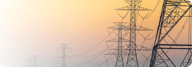
Electrical power transmission uses high voltage to move electric power over transmission lines across long distances, then steps it down through transformers for safe use. It is efficient over distance and easy to convert, control, and distribute.
The rest of this guide covers mechanical transmission in depth (where most sourcing decisions happen), then the electrical side, then the selection and troubleshooting logic that applies across both.
Mechanical Power Transmission Methods
There are five principal methods of mechanical power transmission: gear drives, chain drives, belt drives, couplings, and fluid (hydraulic and pneumatic) power. Each suits a different combination of load, speed, distance, and environment.
Mechanical power is delivered as one of two motions. Rotational motion drives gears, shafts, and pulleys and is the most common form in industrial machinery. Linear motion moves power in a straight line, as in conveyor belts or hydraulic cylinders, and is essential to material handling, packaging, and precision machining. Many systems convert rotational motion into linear motion through components such as lead screws, ball screws, and linear actuators.
Gear Drives
Gear drives use interlocking toothed wheels to transmit power between rotating shafts and are the standard choice when precise speed and torque control matter. Gear geometry is governed by AGMA (American Gear Manufacturers Association) standards, which define quality, tolerance, and rating classes. Common configurations:
Spur gears have straight teeth on parallel shafts. They run smoothly at moderate speeds and transmit torque efficiently. Found in gearboxes, conveyors, and machine tools.
Worm gears pair a worm (screw) with a wheel to achieve high gear reduction in a compact, self-locking design. The reduction ratio is set by the number of worm threads against the number of gear teeth, making them ideal for elevators, hoists, and rotary tables where holding torque matters.
Helical gears run quieter and carry more load than spur gears because multiple teeth engage gradually.
Bevel gears transmit power between shafts that meet at an angle, typically 90 degrees.
When several gears work together as a gear train, the design sets the velocity ratio (the ratio of driving-gear speed to driven-gear speed). A simple gear ratio is calculated by dividing the number of teeth on the driven gear by the number on the driving gear: a 60-tooth driven gear on a 20-tooth driving gear yields a 3:1 reduction, cutting output speed to one third while tripling torque.
Chain drives use linked segments meshing with sprockets, sized by ANSI chain numbers (for example #40, #60, #80, where the number encodes pitch). They handle heavy loads and high torque, transmit power efficiently over longer center distances with positive (non-slip) engagement, and tolerate harsh environments. With proper lubrication, chain drives transmit power at roughly 98 to 99 percent efficiency, with transmission losses of only 1 to 4 percent. They suit conveyors, lifting equipment, and heavy machinery, and they are repairable on site (a damaged chain can be re-linked rather than fully replaced).
Belt Drives
Belt drives transmit power through belts wrapped around pulleys (sheaves). They run quietly, damp vibration, accommodate slight misalignment, and offer built-in overload protection through controlled slip. The main types:
Flat belts are simple and economical but slip more, losing power.
V-belts use a wedge profile for better grip and reduced slippage, and are the industrial workhorse.
Timing (synchronous) belts have teeth that mesh with the pulley, virtually eliminating slip where synchronization is critical.
Belt efficiency depends heavily on tension, wrap angle, and temperature. Rising temperature lengthens belts and increases slip; correct tensioning is the single biggest factor in belt-drive efficiency.
Couplings
Couplings connect two shafts and transmit torque while managing misalignment and shock. The three families:
Rigid couplings (sleeve, clamp, flanged) create a solid connection that transmits high torque with near-zero backlash, but tolerate no misalignment. Use them only where shafts are precisely and permanently aligned, as in machine tools, rolling mills, and test rigs.
Flexible couplings (jaw, disc, gear, bellows, Oldham) accommodate slight misalignment, typically up to about 5 degrees in parallel, angular, or axial directions, and absorb shock and vibration. They protect bearings and seals in pumps, compressors, fans, and motor drives, where small alignment changes from heat, load, and vibration are unavoidable.
Fluid couplings transmit torque through a fluid medium, providing smooth startups and overload protection.
The selection rule reliability engineers apply: if perfect alignment can be guaranteed and held, a rigid coupling transmits more torque with less backlash. If it cannot, a flexible coupling is the safer choice, because any misalignment a rigid coupling cannot absorb transfers as stress straight into bearings and shafts. Match couplings to your equipment from thepower transmission category.
Hydraulic and Pneumatic (Fluid Power) Systems
Fluid power transmits motion through pressurized liquid or gas. Hydraulic systems use pressurized fluid for high-force linear or rotary motion; pneumatic systems use compressed air for faster, lighter-duty actuation. Both deliver high power density, precise control, and inherent overload protection, and they are common in construction equipment, presses, aerospace systems, and automated machinery. Sourcehydraulic components andpneumatic components by pressure and flow rating.
Comparison: Choosing Between Drive Types
The most common selection question is gear vs chain vs belt. This table summarizes the tradeoffs that decide it.
Factor
Gear Drive
Chain Drive
Belt Drive
Efficiency
Highest (up to ~98-99%)
~98-99% with lubrication
High; varies with tension and slip
Slip
None (positive)
None (positive)
Possible (except timing belts)
Load / torque
Highest
High
Moderate to high
Center distance
Short
Medium to long
Short to moderate
Noise
Higher
Higher
Lowest
Lubrication
Required
Frequent
Minimal
Overload protection
None
None
Yes (controlled slip)
Best for
Precise speed/torque, high load
Heavy load over distance, dirty environments
Quiet operation, shock damping, low maintenance
The practical takeaway: efficiency depends more on correct selection, installation, and maintenance than on the drive type itself. A well-maintained belt can outperform a neglected chain.
Components and Accessories That Keep Systems Running
Beyond the primary drive method, every reliable system depends on a layer of supporting components that maintain alignment, reduce friction, and transmit power under stress.
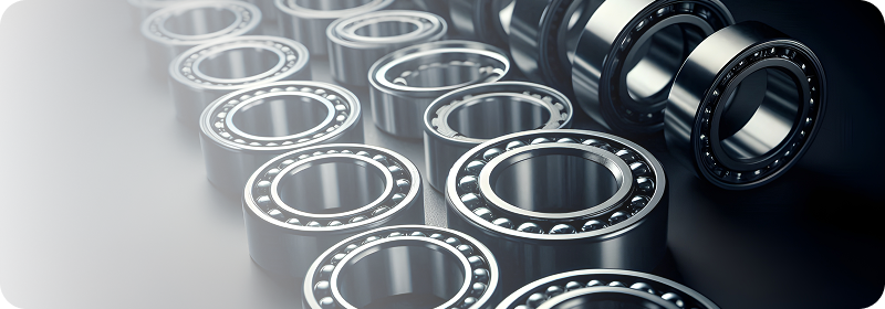
Bearings support rotating shafts and reduce friction, spanning roller, thrust, and spherical designs rated for different load directions. Bearing life is rated by the ISO 281 standard as L10 life, the hours at which 90 percent of identical bearings survive under a given load. Sealed and shielded versions resist contamination in dirty environments.
Bushings protect shafts and provide low-maintenance smooth motion, guarding against torque spikes and thermal expansion. Taper bushings (QD and Taper-Lock styles) let pulleys and sprockets mount and dismount quickly.
Pulleys and sprockets transfer motion from belts and chains while setting speed and torque ratios. Durable units cut slippage, vibration, and wear.
Shaft collars locate and hold components in position along a shaft; clamp styles avoid the shaft damage set-screw styles can cause.
Clutches engage and disengage drive systems, essential for safe starting and stopping of conveyors and industrial machines.
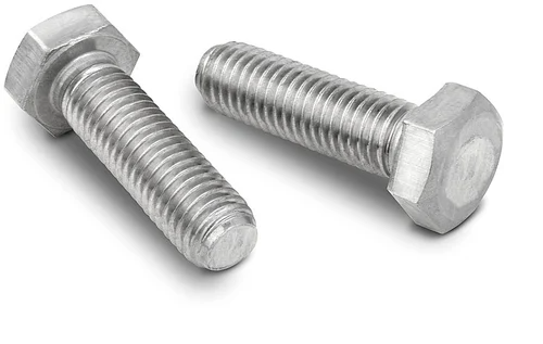
Fasteners (bolts, nuts, keys, pins, set screws) keep components secured under load. High-strength, corrosion-resistant grades are essential in mining, offshore, and energy applications. Sourceindustrial fasteners by grade and finish.
These components routinely work in combination. A gear train sets torque and speed while a chain drive carries that motion over distance, combining the strengths of both. Browse the fullpower transmission range to match accessories to your drive system.
Electrical Power Transmission
When power must travel long distances, electrical transmission carries it at high voltage to minimize current and reduce resistive losses, then steps it down for use. The core elements:
Transmission lines carry energy from generation to substations at high voltage. Efficient delivery depends on conductor design, voltage level, and insulation.
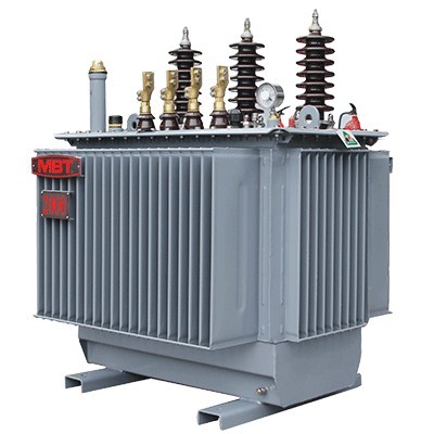
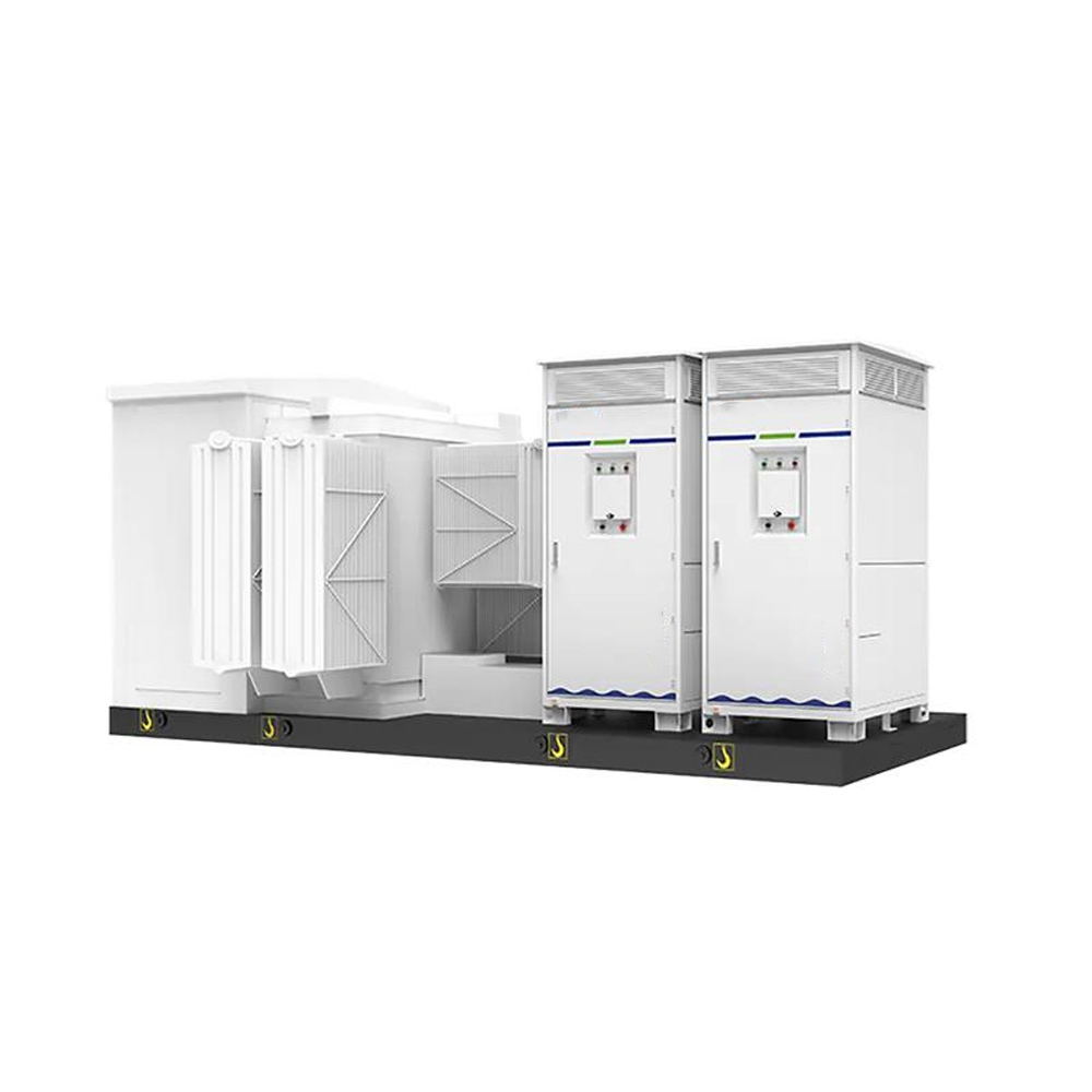
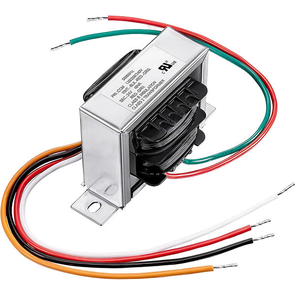
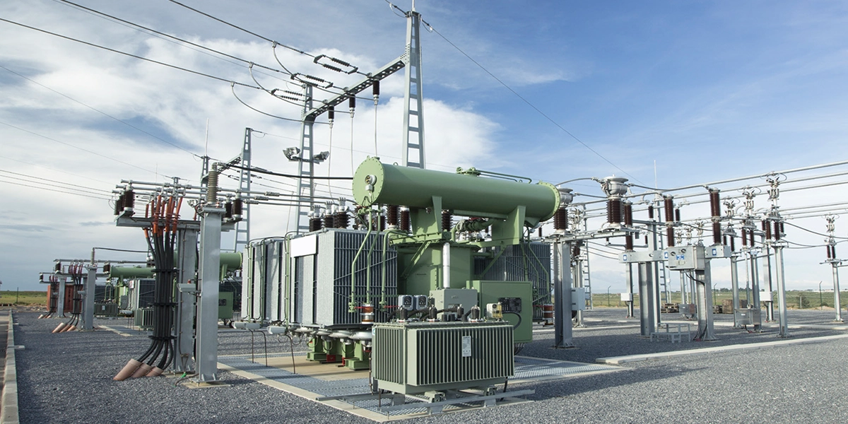
Transformers raise voltage for transmission (step-up) and lower it for safe consumption (step-down), with voltage class and kVA rating determining which unit fits a given load, reducing waste at each stage.
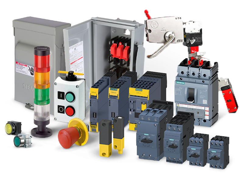
Inside the facility, that delivered power feeds the motors and drives that the mechanical components above put to work. For plant-level electrical distribution and protection, seeelectrical components andtransformers.
How Power Transmission Systems Work Together
A typical industrial drivetrain (motor to conveyor) works in sequence:
The motor serves as the power source.
A rigid coupling connects the motor to a gearbox.
Inside the gearbox, spur or worm gears adjust torque and speed.
A flexible coupling absorbs any shaft misalignment downstream.
The final shaft delivers rotational motion to the conveyor.
The result is smooth operation, low vibration, and consistent performance with minimal energy loss. Each component protects the next: the flexible coupling absorbs movement before it reaches the bearings, and correctly rated bearings keep the shaft true so the gears mesh cleanly.
Factors That Affect Power Transmission Efficiency
To design or maintain a high-performance power transmission system, watch for these factors:
Misalignment
Shaft misalignment disrupts power flow and causes premature wear and breakdowns. In high-speed systems, even slight misalignment significantly reduces efficiency and is one of the leading causes of bearing and coupling failure. Flexible couplings improve alignment tolerance and help maintain smooth energy transfer.
Shock and Vibration
Shock and vibration destroy mechanical components and increase power losses. Couplings and mounts that absorb vibration keep power flow stable and protect equipment during heavy-duty operation. Persistent vibration is also an early warning sign of misalignment, imbalance, or bearing wear.
Gear and Component Selection
The right gear ensures reliable energy transfer: spur gears for simple high-speed torque, worm gears for heavy-duty low-speed reduction. Correct material and size selection minimizes power loss and matches the component to the duty cycle.
Voltage Drop
In electrical systems, voltage drops across long transmission lines waste power. Raising transmission voltage and improving conductor quality both reduce losses and maintain consistent output over distance.
How to Choose the Right Power Transmission Components
Selecting components means balancing performance, cost, durability, and environment. Work through these factors in order:
Load type and magnitude. Distinguish static from dynamic loads. Heavy-load applications need high-capacity bearings, resilient roller chains, heavy-duty pulleys, and robust fasteners.
Speed and precision. Use timing belts for synchronization and helical gears for smooth, quiet motion; match belt or chain choice to noise and precision needs.
Shaft alignment. Rigid couplings only where alignment is guaranteed; flexible couplings everywhere else.
Environment. Dust, moisture, chemicals, and temperature extremes call for sealed bearings, corrosion-resistant materials, and appropriate coatings, especially in mining and offshore energy.
Maintenance profile. For hard-to-reach installations, choose maintenance-free parts such as sealed bearings and self-lubricating bushings.
OEM and spare compatibility. Match accessories to OEM dimensions, tolerances, and standards for safe replacement or upgrade.
Efficiency and total cost. Components that minimize friction lower operating cost across the life of the system, often outweighing a lower purchase price.
When a part is hard to identify or source against an OEM spec, eINDUSTRIFY'sprocurement-as-a-service can match the component for you.
Troubleshooting Common Power Transmission Failures
Most downtime traces back to poor selection, improper installation, or neglected maintenance. The most common failures, their causes, and the part that fixes them:
Symptom
Likely Cause
Solution
Part to Source
Belt slip or failure
Misaligned pulleys, wrong belt type, low tension
Correctly size and tension V or timing belts; match pulley groove
Belts, sheaves
Chain wear and elongation
Poor lubrication, wrong material
Use load-rated roller chain; lubricate on schedule; use hardened sprockets
Roller chain, sprockets
Shaft misalignment
Rigid mounting, thermal expansion
Switch to flexible couplings; locate parts with shaft collars
Flexible couplings, shaft collars
Bearing overheating and seizure
Friction, contamination, overload
Use sealed/shielded bearings rated to the load; verify lubrication
Bearings
Coupling failure
Excess misalignment, fatigue of flexible element
Re-rate coupling to torque and misalignment; inspect element
Replace fasteners periodically in high-vibration service and use locking hardware.
Power Transmission Across Industries
Different sectors rely on tailored component sets:
Automotive and general manufacturing: timing belts, clutches, couplings, and bushings for smooth assembly-line motion, with low-friction bearings on robots and conveyors.
Mining and cement: heavy-duty roller chains, large sprockets, sealed bearings, and robust gear drives that survive continuous loads and abrasive dust.
Power generation (wind, hydro, thermal): precision gear drives and high-strength bearings in gearboxes, with corrosion-resistant fasteners on fans and pumps.
Material handling: conveyors, packaging lines, and presses needing precise, high-efficiency transmission with minimal wear.
For context on scale, the mechanical power transmission equipment market was valued in the tens of billions of dollars and continues to grow with industrialization and manufacturing automation (verify the current figure against a primary market-research source before publishing).
The Bottom Line
A well-designed power transmission system keeps your operation running efficiently, safely, and with minimal downtime. Whether you work with mechanical power on the floor or electrical power to the building, the right components decide the outcome. Understand your system's function, match parts to load, alignment, speed, and environment, protect against shock and vibration, and maintain everything on schedule.
Source Reliable Power Transmission Components with eINDUSTRIFY
eINDUSTRIFY gives industrial buyers the catalog and technical support to source with confidence. Our power transmission components range covers gears, couplings, bearings, belts, chains, pulleys, sprockets, shaft collars, clutches, and fasteners, all from vetted suppliers that meet recognized standards. For hard-to-find or OEM-spec parts,send an RFQ and our team will match it. Reach us at info@eindustrify.com or +1 (888) 774 7632, and register your account for access to the B2B industrial marketplace.
Frequently Asked Questions
What is the difference between mechanical and electrical power transmission?
Mechanical power transmission moves energy through physical components such as gears, belts, chains, and couplings inside machinery, and is most efficient over short distances. Electrical power transmission moves energy as high-voltage electricity over transmission lines across long distances, then steps it down through transformers. Most industrial operations use both.
What are the five types of mechanical power transmission?
The five principal methods are gear drives, chain drives, belt drives, couplings, and fluid (hydraulic and pneumatic) power. Many machines combine them, such as a gear train setting torque and speed with a chain drive carrying motion over distance.
Which is more efficient, a chain drive or a belt drive?
Both can exceed 95 percent efficiency when correctly installed and maintained. A properly lubricated chain drive transmits power at roughly 98 to 99 percent efficiency with positive, non-slip engagement, while belt drives offer quieter operation and overload protection through controlled slip. Efficiency depends more on correct selection and maintenance than on drive type.
When should I use a rigid coupling instead of a flexible one?
Use a rigid coupling only where shaft alignment can be guaranteed and held, such as machine tools and test rigs, because it transmits high torque with no backlash but no tolerance for misalignment. Use a flexible coupling, which tolerates up to about 5 degrees of misalignment, wherever heat, load, or vibration can shift alignment, as in pumps, compressors, and motor drives.
What causes most power transmission failures?
The leading causes are shaft misalignment, incorrect belt or chain tension, inadequate or wrong lubrication, bearing contamination, and fastener loosening under vibration. Precise installation, correct component selection, and scheduled maintenance prevent most unplanned downtime.
How do I calculate a gear ratio?
Divide the number of teeth on the driven gear by the number on the driving gear. A 60-tooth driven gear paired with a 20-tooth driving gear gives a 3:1 ratio, reducing output speed to one third while tripling torque.
Tags: Power Transmission SystemTransmit PowerTransfer Of PowerTransmission SystemPower TransmissionTransmission LinesTransmission And DistributionElectric PowerMechanical Power TransmissionPower SourceEnergy LossesPower Generation