Distribution Transformer Ratings and Specifications: A Buyer's Guide
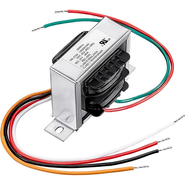
A distribution transformer steps down medium-voltage electricity, typically 4.16 kV to 34.5 kV, to the low voltages used by homes, businesses, and industry, such as 480 V, 240 V, or 120 V. The specifications that define it are its kVA rating, primary and secondary voltage, impedance percentage, basic insulation level (BIL), temperature rise, and cooling class. Each is governed by IEEE C57 or IEC 60076 standards.
This guide explains every rating an engineer or procurement team must specify, compares the main transformer types, and shows how to size a unit correctly. It works by electromagnetic induction between two windings, not by any mechanical or chemical process.
How a distribution transformer works
A distribution transformer transfers power between two circuits through mutual magnetic induction. Alternating current in the primary winding creates a changing magnetic field in the core, which induces a voltage in the secondary winding. The turns ratio between the windings sets the voltage change.
There is no moving part and no current flowing directly between primary and secondary. The voltage is stepped down in proportion to the winding ratio, which is why a transformer can deliver usable low voltage safely and efficiently. Standard terminology and requirements follow IEEE C57.12.00 in North America and IEC 60076 internationally.
Types of distribution transformers
Distribution transformers are classified by insulation method and by mounting. The table below compares the main types; the sections beneath add detail.
Type
Insulation / cooling
Typical kVA range
Best location
Liquid-immersed (oil)
Mineral oil or ester fluid
10 kVA to 10 MVA
Outdoor, utility, high-capacity
Dry-type (cast resin / VPI)
Air and solid insulation
15 kVA to ~5 MVA
Indoor, fire-sensitive sites
Pole-mounted
Liquid-immersed
5 kVA to 500 kVA
Overhead, rural/suburban
Pad-mounted
Liquid-immersed, enclosed
45 kVA to 5 MVA
Underground, urban/commercial
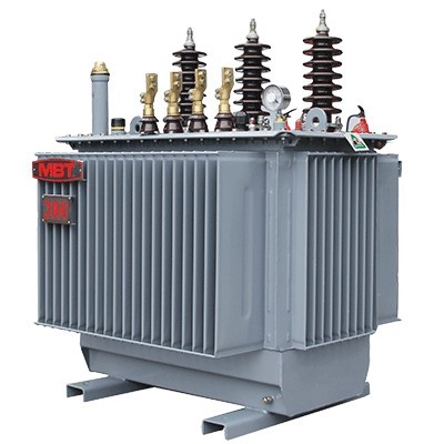
Liquid-immersed (oil-filled) transformers
Liquid-immersed transformers are the most common distribution type. The core and windings sit in a tank of mineral oil or ester fluid that serves as both insulation and coolant. The oil or fluid serves both as an insulator and as a coolant to keep the core at reliable operating temperatures.
They handle the widest capacity range and suit outdoor and high-load service. Cooling is designated by IEEE/IEC classes such as ONAN (oil natural, air natural) and ONAF (oil natural, air forced), covered in the cooling section below. Natural ester fluids offer a higher fire point and biodegradability for environmentally sensitive sites.
Dry-type transformers
Dry-type transformers use air and solid insulation instead of liquid, which removes the fire and leak risk of oil. This makes them the standard choice for indoor installations, hospitals, and other fire-sensitive locations. Common constructions are cast resin and vacuum pressure impregnated (VPI).
Because air is a less effective coolant than oil, dry-types run hotter and use higher-temperature insulation. Dry-type transformers are available in three standard temperature rises, 80°C, 115°C, or 150°C, and most use 220°C-rated winding insulation regardless of design rise, so a lower-rise unit has more reserve for occasional overload.
Pole-mounted and pad-mounted transformers
Pole-mounted and pad-mounted units are defined by how they are installed. Pole-mounted transformers hang on utility poles and convert overhead medium-voltage lines to low voltage for homes and light industry. These transformers can vary in size from as small as 5 kVA to as large as 500 kVA, with voltages up to 35 kV line-to-line.
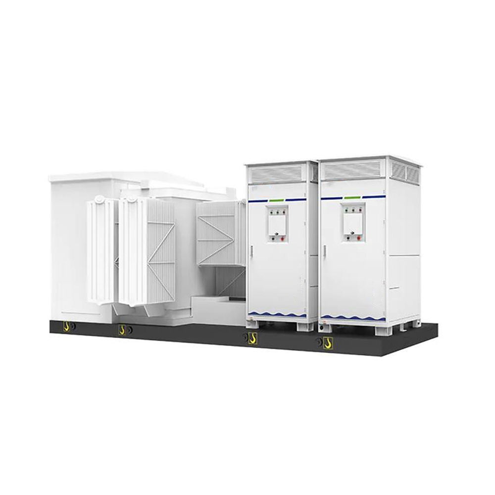
Pad-mounted transformers sit in a locked steel cabinet on a concrete pad, fed by underground cables. A three-phase pad-mounted transformer is a ground-mounted unit generally rated 45 to 5000 kVA, though it can produce up to 10 MVA. Their sealed, tamper-resistant enclosure makes them the standard for urban and commercial underground distribution.
Key ratings and specifications
These are the specifications that define a distribution transformer and that every purchase order should state. The table summarizes them; the detail follows.
Specification
What it defines
Typical values
kVA rating
Apparent power capacity
10 kVA to 10 MVA
Primary voltage
Medium-voltage input
4.16 kV to 34.5 kV
Secondary voltage
Low-voltage output
480 / 240 / 208 / 120 V
Impedance (%Z)
Voltage drop and fault-current limit
~2% to 7%
BIL
Basic insulation level (surge withstand)
60 kV to 150 kV
Temperature rise
Winding rise above ambient
55/65°C (liquid), 80-150°C (dry)
Cooling class
Heat dissipation method
ONAN, ONAF, AN, KNAN
kVA rating (power capacity)
The kVA (kilovolt-ampere) rating is the transformer's apparent power capacity. It differs from kW (real power) by the power factor: kVA is the total power the transformer must carry, including reactive power. Transformers are rated in kVA because they must handle apparent power regardless of the load's power factor.
Standard distribution ratings follow a defined series. The line current is straightforward to derive: for a single-phase unit, current equals kVA times 1000 divided by line voltage; for a three-phase unit, line current equals kVA times 1000 divided by line voltage times 1.732.
Voltage ratings
The voltage rating specifies the primary (input) and secondary (output) voltages the transformer is designed for. In the U.S., primary distribution voltages commonly run from 4.16 kV to 34.5 kV, with secondary voltages of 480 V, 240 V, 208 V, or 120 V. These values vary by region and by IEC versus ANSI convention.
The rating also defines the maximum system voltage and the winding configuration, such as delta or wye on each side. Always confirm both the voltage class and the connection against the system it will serve.
Impedance percentage
Impedance, expressed as a percentage (%Z), is one of the most important and most overlooked specifications. It represents the voltage drop across the transformer at full load and directly determines the available fault current. A lower impedance means a stiffer supply but higher fault current; a higher impedance limits fault current but increases voltage regulation.
Typical distribution transformers fall in the 2% to 7% range. Matching impedance correctly is essential for coordinating downstream protective devices, since circuit breakers sized to the available fault current must clear a fault before it damages the transformer or the load.
Basic insulation level (BIL) and temperature rise
BIL defines the surge voltage the insulation can withstand, protecting the transformer from lightning and switching transients. It is selected to match the system voltage class. Temperature rise defines how hot the windings run above ambient at full load. Standard temperature-rise values are 55°C and 65°C for liquid-filled transformers and 80°C, 115°C, or 150°C for dry-types, all based on a maximum 40°C ambient.
Temperature rise drives service life directly. Operating roughly 8 to 10°C above the rated temperature can cut a transformer's insulation life by more than half, which is why correct loading and cooling are critical.
Cooling class
The cooling class, marked on the nameplate per ANSI/IEEE, describes how the transformer dissipates heat. ONAN (oil natural, air natural) and ONAF (oil natural, air forced) are the most common classes in distribution and power transformers using mineral oil, with ONAN as the passive base rating and ONAF adding fans to carry more load.
Forced cooling raises capacity meaningfully. Under IEEE C57.12.10, transformers rated below 2500 kVA three-phase or 833 kVA single-phase typically receive a 15% capacity boost when forced air cooling is applied. Ester-filled units use the K designation, such as KNAN.
Single-phase vs. three-phase
The phase configuration determines where a transformer is used. Single-phase transformers have one primary and one secondary winding and serve residential and light loads. Three-phase transformers have three sets of windings and supply the higher, balanced power that commercial and industrial facilities require.
Factor
Single-phase
Three-phase
Windings
One set
Three sets
Typical use
Residential, light commercial
Commercial, industrial
Power delivery
Lower loads
Higher, balanced loads
Connection
Simple
Delta or wye (vector group)
Three-phase units are specified with a vector group, such as Dyn11, that defines the primary and secondary connections and their phase relationship.
Tap changers: DETC vs. OLTC
A tap changer adjusts the turns ratio to correct output voltage as input voltage or load varies. There are two types, and the distinction matters for specification. A de-energized tap changer (DETC) can only be adjusted with the transformer switched off, and is typical on distribution units with steps such as ±2.5% and ±5%.
An on-load tap changer (OLTC) adjusts voltage while the transformer is energized and carrying load, and is used where continuous voltage regulation is essential. Confirm which your application requires, because retrofitting is costly.
How to size and select a distribution transformer
Work through these steps to specify correctly the first time.
Calculate the load in kVA. Total the connected load and apply demand and growth factors. Size the transformer so normal load sits comfortably below the rated kVA.
Set the voltage class and configuration. Match primary and secondary voltage and the delta/wye connection to the system.
Specify impedance and BIL. Choose impedance to coordinate with downstream protection, and BIL to match the voltage class.
Select insulation type and temperature rise. Liquid-immersed for outdoor and high capacity, dry-type for indoor and fire-sensitive sites; lower temperature rise gives more overload reserve.
Choose the cooling class and efficiency level. Specify ONAN/ONAF or dry-type cooling, and confirm compliance with the DOE efficiency rule (10 CFR Part 431) or IEC equivalent.
Correct sizing protects efficiency and life. Overloading causes overheating that shortens insulation life, while significant underloading wastes capital and runs at lower efficiency.
Efficiency, loading, and maintenance
Efficiency is now regulated. In the U.S., distribution transformers must meet minimum efficiency under DOE 10 CFR Part 431, which targets the no-load and load losses that run continuously over the unit's life. Specifying an efficient unit lowers lifetime energy cost, not just purchase price.
Maintenance differs by type. Liquid-immersed units need periodic oil testing, including dissolved gas analysis (DGA) and dielectric strength tests, plus bushing and gauge checks. Dry-types need clean ventilation, airflow verification, and periodic inspection for dust and winding conditions. Both benefit from thermal scanning and load monitoring to catch problems early.
Frequently asked questions
What is a distribution transformer?
A distribution transformer steps down medium-voltage electricity (typically 4.16 kV to 34.5 kV) to the low voltages used by end users, such as 480 V, 240 V, or 120 V. It works by electromagnetic induction and delivers safe, usable power to homes, businesses, and industry.
What does the kVA rating mean?
The kVA rating is the transformer's apparent power capacity, the total power it can carry including reactive power. It differs from kW by the power factor. Select a kVA rating that comfortably exceeds the peak load to avoid overheating.
What is the transformer impedance percentage?
Impedance (%Z) is the voltage drop across the transformer at full load, typically 2% to 7%. It determines the available fault current and affects voltage regulation, so it must be coordinated with downstream protective devices.
What is the difference between oil-filled and dry-type transformers?
Oil-filled (liquid-immersed) transformers use oil for insulation and cooling and suit outdoor, high-capacity service. Dry-type transformers use air and solid insulation, eliminating fire and leak risk, which makes them ideal for indoor and fire-sensitive installations. Dry-types run hotter and use higher-temperature insulation.
What does temperature rise mean on a transformer?
Temperature rise is how far the windings heat above ambient at full load, standardized at 55/65°C for liquid units and 80/115/150°C for dry-types at a 40°C ambient. Operating about 8 to 10°C above the rated temperature can halve insulation life.
What is the difference between DETC and OLTC tap changers?
A de-energized tap changer (DETC) is adjusted only with the transformer off, typical on distribution units. An on-load tap changer (OLTC) adjusts voltage while the transformer is energized, used where continuous voltage regulation is required.
What standards govern distribution transformers?
IEEE C57.12.00 covers general requirements for liquid-immersed units, IEEE C57.12.20 covers overhead types, IEC 60076 is the international standard, and DOE 10 CFR Part 431 sets U.S. efficiency requirements.
Source distribution transformers through eINDUSTRIFY
eINDUSTRIFY is a premier global B2B marketplace for industrial supplies, connecting procurement, MRO, and utility teams with vetted suppliers of distribution transformers, where lead times and total project cost often outweigh unit price alone in the sourcing decision. Every seller is vetted, so you source genuine, standard-compliant units with the ability to compare ratings, types, and specifications in one place.
Browse the Transformers category, along with related Generators, Energy Storage, and Electrical categories. For utility-scale procurement, hard-to-find ratings, or full project sourcing,submit an RFQ and our team will match you to the right suppliers with fast price comparison. These transformers serve the Power Generation and Electric Utilities sectors directly. Call 1-888-774-7632 or email info@eindustrify.com to get started.
Tags: distribution transformer kVA rating transformer specifications oil-filled transformer dry-type transformer IEEE C57
















 vs Automatic Transfer Switch (ATS) for Data Centers.png)