Why Overload Relays Are Essential in Power Generation and Electrical Control
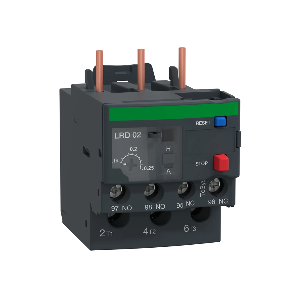
An overload relay is a motor-protection device that continuously monitors current and disconnects the motor when it draws sustained overcurrent for too long, preventing winding insulation from burning out. It protects against the chronic 115 to 150 percent overcurrent that fuses and breakers ignore, using an inverse-time trip curve set by class (Class 10, 20, or 30). Correct selection turns a destructive thermal event into a controlled, recoverable stop.
Power generation plants, data center generator halls, and large-scale process facilities share a common vulnerability: motor failure at the wrong moment costs not just the motor, but every part of the process that motor was keeping alive. Inside every starter protecting those assets sits a device that procurement routinely treats as a commodity, the overload relay. That classification is where motor fleet reliability quietly erodes.
When correctly selected and calibrated, an overload relay converts a destructive thermal event into a controlled stop. When it is wrong for the application, whether through a mismatched trip class, an incorrect current setting, or a thermal design in a high-ambient enclosure, the motor runs until it cannot.
The failure mode is rarely sudden. A process pump develops bearing drag over weeks, drawing higher current on every shift. A cooling fan in a gas turbine inlet picks up contamination and runs above the nameplate before anyone notices. A compressor auxiliary operates against a partially closed valve for months. Each condition is survivable if overload protection responds correctly, and each becomes an unplanned outage if it does not.
What does an overload relay actually do?
An overload relay continuously tracks what the motor actually draws against what its nameplate says it should carry, and acts when that gap stays open too long. What distinguishes it from a fuse or breaker is the time element. The table below shows where each device sits.
Device
Protects against
Response time
Current level
Fuse / circuit breaker
Short-circuit faults
Milliseconds
Thousands of amps
Overload relay
Sustained overcurrent
Seconds to minutes
115 to 150% of FLC
MPCB (motor protection breaker)
Both, in one frame
Both
Both ranges
Fuses and breakers clear fault-level currents in milliseconds before arc damage occurs. An overload relay is calibrated for a different threat: sustained overcurrent at 115 to 150 percent of nameplate, the kind that never triggers instantaneous protection but destroys winding insulation over minutes of accumulated thermal stress.
When the relay detects that condition persisting beyond its trip curve, it opens an auxiliary contact that drops out the contactor coil and disconnects the motor. That separation between the relay's thermal-detection role and the contactor's power-switching role is the architecture that keeps a controlled shutdown from escalating into a contact-welding fault. Adjustable current settings let teams align protection to each motor's nameplate rather than applying a blanket value that either nuisance-trips light loads or permits excess thermal stress.
Why is motor overload such a big problem?
Overloading is one of the leading causes of motor failure in industry. Overload protection exists to protect motor windings, because overload protection is about motor temperature, not conductor protection, which upstream devices handle. When a motor runs above rated current, copper losses increase, winding temperature rises, and insulation life shortens with each overheating event.MCR Safety
Real-world overload conditions come from many sources. Common examples include jammed pumps in water and wastewater plants, misaligned couplings on compressors, fouled fan blades in HVAC systems, and motors undersized for the loads they now drive. In three-phase systems, single-phasing or severe phase imbalance can force the remaining phases to carry excessive current, pushing the motor into dangerous thermal stress.
For procurement and reliability teams responsible for motor fleets, these are hard costs. Each burned-out motor means replacement cost, labor, potential secondary damage to pumps or conveyors, and unplanned downtime that can reach hundreds of thousands of dollars per event in high-throughput facilities.
How do overload trip units and trip classes work?
Overload relays use the inverse-time principle: the higher the current above the setting, the faster they trip. This behavior is expressed through trip classes, which define how quickly the relay operates at a defined multiple of motor current. Time as well as current matters for AC induction motors because they draw significantly more than full rated current, often 600 percent or more, during startup.
Trip class
Max trip time at ~600% FLC
Typical loads
Class 5
5 seconds
Fast-response, submersible pumps
Class 10
10 seconds
Standard motors, pumps, fans
Class 20
20 seconds
General-purpose, longer starts
Class 30
30 seconds
High-inertia: conveyors, compressors, mixers
Class 10 suits standard industrial motors and general applications, Class 20 is common for general-purpose motors, and Class 30 suits high-inertia loads like large fans, flywheels, or centrifugal equipment. Trip classes are defined in IEC 60947-4-1 and used across manufacturer catalogs.
In the United States, NEC Article 430 governs overload sizing. Typical practice sets the overload at 125 percent of full-load current for motors with a 1.15 service factor, and 115 percent for those without that margin. Adjustable settings let you align protection to the nameplate and starting characteristics rather than a single fixed value.
What makes electronic overload relays a better fit for critical loads?
Electronic overload relays use current transformers and microprocessor logic instead of mechanical bimetal strips. They calculate true RMS current and model motor heating in software, measuring each phase independently. This digital approach provides much higher measurement accuracy, typically around plus or minus 2 to 5 percent, and ensures consistent performance regardless of ambient temperature changes.
Factor
Thermal (bimetallic)
Electronic
Sensing
Heat from bimetal strip
CT + microprocessor, true RMS
Accuracy
Affected by ambient temp
±2 to 5%, ambient-independent
Phase loss detection
Limited
Fast, per-phase
Extra functions
None
Jam, ground-fault, underload
Data output
None
%TCU, %FLA, fault history
Reset
Manual / auto
Manual, auto, remote
Because they monitor each phase separately, electronic relays detect phase loss and severe imbalance quickly, often before the motor overheats. Electronic relays can provide data such as percentage of thermal capacity utilization, percentage of full-load amps, time-to-trip, RMS current, and ground-fault current, which helps operators run diagnostics and predict when a relay is at risk of tripping. Many add jam detection and underload protection for pumps running dry or conveyors losing load.
Modern units feature adjustable current settings, selectable trip classes, and password-protected configuration. For procurement teams standardizing across sites, that flexibility means fewer part numbers, better coverage of motor sizes, and protection that adapts as processes change.
Where do overload relays sit across industrial facilities?
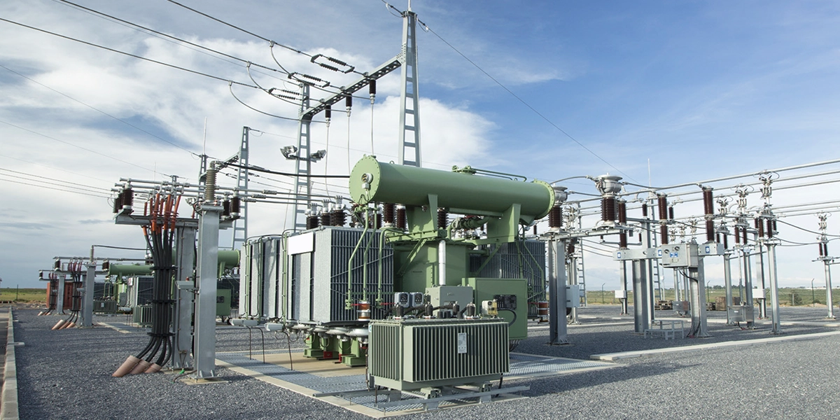
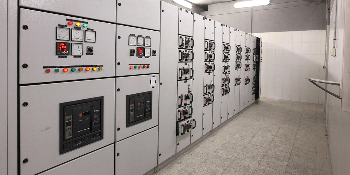
Overload relays are installed inside motor control centers or individual starters, alongside the contactor they control and the upstream devices that handle fault-level events. The motors they protect, including auxiliary cooling fans, process pumps, compressor drives, conveyors, and mixers, are rarely the headline equipment on a plant's asset register. Their failure consequences are not modest.
A cooling fan motor failure in a gas turbine auxiliary system does not damage the turbine directly. It can, however, force a derating or unit trip that costs orders of magnitude more than the motor itself. A process pump motor that fails during peak production does not just stop that pump; it stops everything downstream that pump was feeding. These risks sit squarely in the Power Generation and Data Centers facilities eINDUSTRIFY serves.
This is why overload protection in low-voltage motor circuits cannot be treated as a lower tier of the protection philosophy simply because the voltage is lower. Fuses and breakers clear short-circuit faults upstream. Specialized protection relays guard medium-voltage switchgear. Overload relays handle the specific, chronic risk of sustained overcurrent in the motors that keep critical processes running.
How are smart overload relays changing motor protection?
Smart, networked overload relays extend the same core protection into connected automation and Industry 4.0. Advanced electronic modules share real-time data on individual phase currents, average load, thermal capacity used, and fault history over industrial networks such as EtherNet/IP, Modbus TCP, and PROFIBUS.
This connectivity enables predictive maintenance. Teams can trend running current, detect slowly increasing load on pumps and fans, or spot frequent near-trip conditions that point to worn bearings, fouled filters, or partially blocked lines. In modern plants, these parameters flow into SCADA systems or historians, where they feed asset-health dashboards and scoring models.
The market is moving in this direction. Industry analysis indicates electronic and smart overload relays now account for more than half of the global overload relay segment and are growing faster than traditional thermal units. For new MCCs, large retrofits, and mission-critical assets in power generation, oil and gas, and large-scale manufacturing, electronic overloads are increasingly the default rather than a premium option.
How should procurement think about adjustable overload settings?
For teams standardizing protection across large fleets, the adjustable current setting is the most operationally significant specification on the relay. It defines the thermal boundary the motor may operate within. Set it too conservatively and nuisance trips interrupt production; set it too liberally and the protection no longer restrains the damage it exists to prevent.
A well-specified adjustable relay lets one part number protect motors across a range of ratings within the same frame size, directly reducing stocked SKUs across a multi-site inventory. That is a procurement efficiency that compounds at fleet scale. Trip class adds a second dimension, and the two cannot be treated independently.
For pumps and fans that reach full speed quickly, Class 10 provides tight, responsive coverage. For high-inertia conveyors, compressors, or mixers, that same Class 10 setting will trip on a perfectly healthy start because acceleration current exceeds the threshold longer than the relay tolerates. Specifying Class 20 or 30 for those loads allows the start to complete while still responding decisively to real overloads at running speed.
Applying a single default trip class across a mixed fleet, as happens when relays are treated as a commodity purchase, is one of the more consistent sources of unexplained nuisance trips in industrial motor circuits, and one of the easier to eliminate with application-specific selection at the procurement stage.
Why overload relays matter for safety and fire risk
The protection function extends well beyond the motor itself. Sustained overcurrent generates heat not only in the windings but in every conductor, termination, lug, and busbar between the motor and its protective devices. In the densely wired environment of an MCC, that heat accumulates in spaces with limited thermal dissipation. A relay that trips at the correct threshold limits how long those conductors operate above rated temperature, directly reducing the chance that an overloaded termination transitions from a thermal problem into an ignition source.
NFPA 70E, the standard governing electrical safety in the workplace, treats thermal hazards in energized equipment as a defined arc flash and fire risk, not a hypothetical one. NEC Article 430 establishes motor overload protection as a mandatory element of the branch circuit, specifically because thermal failure modes in unprotected motor circuits have a documented path to electrical fires.
Industrial insurance underwriters have followed that logic. Many now require documented evidence that motor branch circuits are protected within NEC-compliant overload settings as a condition of coverage, and incident investigations after MCC fires routinely identify absent or incorrectly set overload protection as a contributing factor. For plant safety officers and EHS teams involved in procurement, the overload relay carries simultaneous implications for asset protection, NFPA 70E compliance, and the facility's insurance position. It is one of the few line items in a starter specification that touches all three at once.
Bringing it together: overload relays as a reliability decision
When a starter or MCC lineup is specified or retrofitted, the overload relay is the component most consistently treated as an afterthought: sized by habit, ordered at the lowest price, and set to a default carried forward from the previous project. That habit is where motor fleet reliability erodes without a clear cause, because the failures appear as maintenance events rather than procurement decisions.
The choice between thermal and electronic designs, the trip class matched to each load, and the current setting aligned to each motor's nameplate determine how motors behave under the stress conditions guaranteed to occur: process upsets, phase disturbances, mechanical wear, and unplanned load changes. Those decisions compound across a fleet of hundreds or thousands of motors.
Frequently Asked Questions
1. What does an overload relay do?
An overload relay continuously monitors motor current and disconnects the motor when it draws sustained overcurrent beyond its trip curve. It protects winding insulation from the chronic 115 to 150 percent overcurrent that fuses and breakers ignore, opening an auxiliary contact that drops out the contactor.
2. What is the difference between an overload relay and a circuit breaker?
A circuit breaker or fuse clears short-circuit faults in milliseconds at thousands of amps. An overload relay handles sustained overcurrent over seconds to minutes, protecting against motor overheating rather than conductor faults. A motor protection circuit breaker (MPCB) combines both functions in one frame.
3. What is a trip class on an overload relay?
Trip class defines how fast the relay trips at a defined overcurrent, usually about 600 percent of full-load current. Class 10 trips within 10 seconds, Class 20 within 20, and Class 30 within 30. Higher classes allow longer motor starts before tripping.
4. Which trip class should I use?
Use Class 10 for pumps and fans that reach speed quickly, and Class 20 or 30 for high-inertia loads such as conveyors, large compressors, and mixers that need longer acceleration. Applying one default class across a mixed fleet is a common cause of nuisance trips.
5. What is the difference between thermal and electronic overload relays?
Thermal relays use a bimetallic strip heated by current and are affected by ambient temperature. Electronic relays use current transformers and a microprocessor for true-RMS, ambient-independent accuracy of about ±2 to 5 percent, plus per-phase monitoring, jam and ground-fault detection, and diagnostic data.
6. How do I size an overload relay per the NEC?
NEC Article 430 typically sets the overload at 125 percent of full-load current for motors with a 1.15 service factor, and 115 percent for those without. The relay's adjustable setting is then aligned to the motor nameplate and starting characteristics.
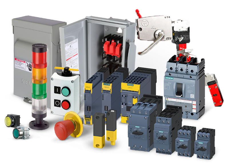
Source overload relays through eINDUSTRIFY
eINDUSTRIFY carries overload relay product lines from Eaton, Schneider Electric, Siemens, and ABB, the manufacturers whose components are already specified in the motor control standards your engineering teams work to. Browse theIndustrial Control and overload relay range to review designs by trip class, current range, and network protocol, along with related Motors and Electrical categories.
If you are working from a motor list or a starter schedule across multiple sites, submit your requirements through theRFQ form. A focused application review, aligned to your load types, criticality tiers, ambient conditions, and network integration requirements, can turn overload relay procurement from a commodity line item into a documented lever for fleet uptime, electrical safety compliance, and long-term asset health. Call 1-888-774-7632 or email info@eindustrify.com to get started.
Tags: overload relay motor protection trip class selection thermal and electronic overload relays motor control NEC Article 430