Top 5 Generator Protection Devices for Reliable Power Generation
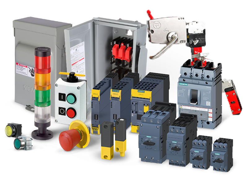
Generator protection devices are the coordinated hardware that isolates faults, transfers load, and clamps transients before they damage the machine or cascade through the system. The five essentials are the generator breaker, automatic transfer switch, surge protective device, ground fault device, and voltage and phase monitor. Selected and set together, they distinguish a local feeder fault from a system-level problem.
Picture a single-phase-to-ground fault on a downstream motor feeder that trips the generator breaker, shuts down an entire plant, and turns what should have been a localized outage into a full-site incident report. In post-incident reviews, the root cause is usually misapplied or poorly coordinated protection devices.
Today's generators power hospital life-safety systems, high-density data center racks, and renewable-heavy microgrids, often within the same campus. Yet many rely on a patchwork of legacy breakers, transfer switches, and relays never designed to work together or to meet current coordination expectations from NFPA 110 and the NEC.
The five devices at a glance
Each device answers a distinct failure mode. This table is the specification shortcut.
Device
Failure mode it addresses
Governing standard
Generator breaker (GCB)
Fault current from the machine; nuisance trips on motor starts
IEEE C37.102, IEEE C37.013
Automatic transfer switch
Load stranded on a failed source; uncoordinated transfers
UL 1008, NFPA 110 Ch. 6
Surge protective device
Transient overvoltage damaging electronics
UL 1449
Ground fault device
Low-level ground faults below overcurrent pickup
NEC 700/701, IEEE C37.101
Voltage and phase monitor
Slow-burn damage from unbalance, phase loss, undervoltage
IEEE C37.2 (27, 47, 59)
Protection engineers reference these functions by ANSI device number, standardized in IEEE C37.2. The system assigns numerical designations from 1 to 99 to specific device functions, enabling precise schematic representation across the industry.
ANSI number
Function
27 / 59
Undervoltage / overvoltage
32
Reverse power
40
Loss of field
46
Negative sequence (current unbalance)
47
Phase sequence voltage
50 / 51
Instantaneous / time overcurrent
64
Ground detector
87G
Generator differential
Protection philosophy 101: before you pick devices
Good protection devices are selected and set from a clear understanding of priorities and operating scenarios.
At the machine level, protection functions keep stator windings, rotor circuits, insulation systems, and excitation hardware within safe thermal and dielectric limits. IEEE C37.102-2023 exists specifically to assist the protection engineer in applying relays to protect generators from internal electrical faults, system faults, and abnormal operating conditions.
At the system level, protection must prevent faults on one feeder or bus from cascading into an entire emergency power system or microgrid. On the human side, protective devices limit shock and arc-flash energy by clearing faults quickly and selectively, aligning with NEC and NFPA expectations.
These objectives overlap. A ground fault left undetected may not destroy the generator, but it elevates touch voltages and arc-flash risk system-wide. An oversensitive generator breaker that trips on every downstream disturbance technically protects the machine while defeating the purpose of having standby power available.
Adequate protection therefore starts with a clear view of what you are protecting, in what priority order (people, generator, loads, upstream grid), and under which operating scenarios.
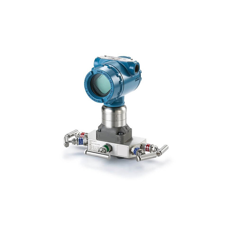
Generator breaker: your first and last line of defense
What a generator breaker does
A generator breaker (generator circuit breaker, or GCB) is the central switching and protective interface between the generator and the rest of the system. It connects or isolates the machine from the main bus or step-up transformer while interrupting any fault current the generator can supply.
It typically sits at the generator terminals or on the low-voltage side of the step-up transformer. It must combine adequate continuous current rating, fault-interrupting strength, mechanical endurance, and a clean interface to the protection relay that sends it trip commands.
Sizing and rating beyond "amps on the nameplate"
Properly sizing a generator breaker means checking both its thermal rating for expected load, with growth margin, and its short-circuit rating against the maximum generator-source and system-source fault currents at its location. Matching full-load amps alone is insufficient.
Generators have high X/R ratios that create asymmetrical fault currents with high peak values, the same interrupting capacity and trip-curve coordination that governs breaker selection elsewhere in the plant, but tested against a harder duty here. You must confirm the breaker's tested asymmetry capability and ensure its interrupting and making ratings are compatible with the relay's intended clearing times.
Coordination with downstream protection
Coordination issues, not undersizing, cause many of the most disruptive generator trips. The classic failure is a downstream fault in a transfer switchboard tripping the generator breaker instead of the feeder or branch breaker.
To prevent this, plot the generator breaker's time-current characteristic against the downstream breakers so downstream devices operate first across the expected fault range. Settings must also account for motor inrush and transformer energization, so normal starting currents do not appear as faults.
Checklist for specifying a generator breaker
Specification
What to verify
Voltage class and BIL
Matches generator terminals or transformer secondary
Continuous current rating
Margin for load growth, paralleling, export operation
Interrupting and making capacity
Against calculated generator-source and system-source fault duties
Short-time withstand rating
Adequate for longest plausible clearing time
Selective coordination
Confirmed by plotted curves, not assumptions
Mechanical endurance
Matches expected operations in testing and load-shedding
Automatic Transfer Switch (ATS): getting power to the right loads at the right time
Why ATS selection is a protection decision
An automatic transfer switch is more than a large contactor. It continuously monitors the preferred source, decides when to bring the generator online, and controls how and when loads move between sources.
Its logic directly affects which loads experience a momentary outage, which transfers occur without interruption, and how well the generator breaker and downstream protection remain coordinated during source changes. Transfer switches are designed and tested to UL 1008, the Standard for Safety of Transfer Switch Equipment, which verifies manufacturer ratings for reliability and durability.
Core ATS types and when to use them
There are three transition types, and confusing them is a common specification error.
Transition type
Sequence
Interruption
Best for
Open transition
Break-before-make
~40 ms
Resistive and small motor loads
Closed transition
Make-before-break
None (momentary parallel)
Hospitals, data centers, sensitive loads
Delayed transition
Break, pause, make
Intentional pause
Large motor and transformer loads
An open transition switch uses a break-before-make sequence to prevent inadvertent interconnection, and power is interrupted for approximately 40 milliseconds. Closed transition switching momentarily parallels the two live sources and is used where interruption of even a few milliseconds is unacceptable, such as hospital operating rooms, though it typically requires approval from the utility and the authority having jurisdiction. Delayed transition adds an intentional pause so residual voltages and transients can decay.
Key specs engineers often miss
Beyond ampere rating, three attributes strongly influence protection performance: source-sensing thresholds, transfer timing, and withstand and closing ratings.
Voltage and frequency pickup and dropout settings determine when the ATS judges a source good or bad. Transfer and retransfer delays shape how often the generator starts and how long it carries load. The withstand and closing rating (WCR) must match available fault current so the switch can safely make and break under emergency conditions. Some manufacturers perform the optional UL 1008 short-time withstand test, with short-time ratings commonly specified to 0.5 seconds.
Mini use cases
In hospitals, NFPA 110 and NFPA 99 drive separate life-safety, critical, and equipment branches. NFPA 110 classifies systems by Class (hours of fuel), Type (maximum seconds without acceptable power), and Level (life-safety impact). A Type 10, Level 1 system must restore emergency power within 10 seconds, and NFPA 110 Section 6.3.3 requires first-priority emergency loads to switch to the emergency bus upon sensing available power. A manual transfer switch cannot meet Type 10; an automatic switch is mandatory.
In data centers, closed-transition ATS schemes pair with UPS systems, so the ATS must transfer without causing voltage steps or sags that force the UPS fleet to battery unnecessarily. These facilities are served by theData Centers sector, whereEnergy Storage backup is part of the same protection chain.
Surge protector: shielding against transient overvoltage
Why generators are hard on sensitive loads
Generator systems experience frequent switching events, steep load steps, and occasional utility disturbances or nearby lightning. All of these can cause transient overvoltages that stress insulation and damage sensitive electronics.
Without a dedicated surge protective device, these fast spikes ride on top of the generator's output. They silently shorten the life of transfer switch controls, building automation systems, and IT hardware.
SPD basics for generator systems
Surge protective devices are classified Type 1, Type 2, and Type 3 under UL 1449, based primarily on where they are installed and the surges they intercept.
SPD type
Installation point
Surge intercepted
Type 1
Service entrance, main switchboard
Large external surges, lightning
Type 2
Distribution and generator switchboards
Residual and internally generated
Type 3
At the point of use
Low-energy transients at the load
Designing a layered surge protection strategy
An effective strategy combines all three types, so no single device absorbs every surge. The typical pattern installs Type 1 protection at the service or main emergency switchboard, Type 2 devices on generator and critical distribution panels, and Type 3 protection at endpoints such as IT racks, control panels, and medical imaging loads.
Common mistakes
Two frequent errors are installing a single SPD and assuming whole-facility protection, and overlooking grounding and bonding quality, which is essential for any SPD to function. A third is selecting SPDs solely on surge current rating (kA) while ignoring residual let-through voltage, which is what actually appears at the terminals of sensitive equipment during a surge.
Ground fault devices: catching the faults you cannot see
Ground fault protection vs overcurrent protection
Many dangerous ground faults do not produce enough current to trip standard overcurrent devices quickly, especially when the fault path is resistive or involves long cable runs. A ground fault device detects exactly these low-level faults that overcurrent relays miss.
How ground fault protection works in generator systems
In generator applications, ground-fault protection is often provided by zero-sequence current sensors or residual-current relays that compare the vector sum of the three-phase currents, and sometimes the neutral, to a pickup threshold.
More advanced schemes, such as restricted earth-fault protection on wye-connected machines, use separate current transformers on each phase and the neutral. This distinguishes internal stator ground faults from external faults, so the relay trips only when the generator itself is at risk.
Code-driven decisions for emergency systems
NEC and NFPA requirements complicate ground-fault decisions for emergency systems, because unwanted tripping of the source can be more dangerous than a controlled alarm. The NEC defines three backup system categories: emergency systems (Article 700), legally required standby (Article 701), and optional standby (Article 702).
Many designers implement a ground-fault alarm only on emergency generators, using ground-fault trip on downstream distribution. This lets a fault be located and cleared without dropping the entire source.
Practical configuration tips
Set pickup high enough to ride through transformer inrush and normal leakage, but low enough to detect genuine ground faults in reasonable time. Equally important, document and verify the neutral-to-ground bonding point for the generator or generator bus. Misplaced or duplicate bonds can bypass ground-fault elements or create circulating currents that produce misleading measurements and nuisance alarms.
Voltage sensor and phase monitor: preventing slow-burn failures
Why is voltage and phase monitoring non-negotiable now
Overvoltage, undervoltage, phase loss, and phase unbalance quietly damage equipment, which is why a dedicated voltage sensor and phase monitor are no longer optional. These relays give early warning and, when wired to trip or alarm, disconnect vulnerable loads before a slow-burning issue becomes a major failure.
What a phase/voltage monitoring relay watches
A typical three-phase monitoring relay tracks line-to-line or line-to-neutral voltage, checks that each phase stays within an over- and under-voltage band (ANSI 27 and 59), and verifies that all three phases are present in correct sequence (ANSI 47).
It also measures phase-to-phase imbalance. If deviation exceeds a set percentage for longer than a defined delay, it raises an alarm or opens a control contact to protect connected equipment.
Applications across standby, prime, and microgrids
In standby and rental sets feeding mixed motor loads, voltage and phase monitors ensure that a loose connection, failed fuse, or contactor problem does not leave a motor running on two phases.
In microgrids and hybrid systems with renewables, these relays provide a straightforward way to monitor voltage quality and phase balance as sources come online and offline, supporting more sophisticated controls without relying entirely on them.
Configuration pointers
In practice, many engineers set phase-unbalance pickup at 5 to 10 percent, with a short time delay to ride through brief disturbances without ignoring persistent problems.
Place monitoring relays at key distribution points: the generator output, main emergency switchboard, or large motor control centers. This gives operations teams actionable information about where a voltage or phase issue is developing, rather than a downstream symptom.
Turning devices into a protection strategy
Choosing the right generator protection devices is only half the job. Making them work together as a layered, coordinated system is what actually prevents minor faults from escalating into full-site outages.
Treat the generator breaker, ATS, surge protection, ground fault devices, and voltage and phase monitors as complementary tools rather than standalone components. Done well, this aligns machine safety, system reliability, and code requirements into a single coherent scheme that is easier to operate, troubleshoot, and upgrade.
Frequently asked questions
What are generator protection devices?
Generator protection devices are the coordinated hardware that isolates faults, transfers load, and clamps transients to protect the machine, the system, and personnel. The five essentials are the generator breaker, automatic transfer switch, surge protective device, ground fault device, and voltage and phase monitor.
What is the difference between a generator circuit breaker and a standard breaker?
A generator circuit breaker sits at the machine terminals and must interrupt fault current the generator itself supplies. Because generators have high X/R ratios producing asymmetrical fault currents, a GCB requires tested asymmetry capability and making ratings that standard distribution breakers may not provide.
What is the difference between open and closed transition ATS?
An open transition switch uses break-before-make, interrupting power for roughly 40 milliseconds. A closed transition switch uses make-before-break, momentarily paralleling both live sources for a seamless transfer, and is used where any interruption is unacceptable. Closed transition typically requires utility and AHJ approval.
What does NFPA 110 Type 10 mean?
NFPA 110 classifies emergency power systems by Class, Type, and Level. Type defines the maximum seconds the load terminals may be without acceptable power, so Type 10 means power must be restored within 10 seconds. Level 1 applies where equipment failure could cause loss of life.
What are ANSI device numbers?
ANSI device numbers, defined in IEEE C37.2, assign numerical designations from 1 to 99 to protective device functions. Common generator functions include 27 and 59 for under and overvoltage, 32 for reverse power, 40 for loss of field, 46 for negative sequence, 50 and 51 for overcurrent, 64 for ground detection, and 87G for generator differential.
Should an emergency generator ground fault trip or alarm?
Many designers configure ground-fault alarm only on emergency generators, applying ground-fault trip on downstream distribution instead. This allows a fault to be located and cleared without dropping the emergency source, since unwanted tripping can be more dangerous than a controlled alarm.
What SPD type do I need for a generator system?
Use all three in layers. Type 1 at the service entrance or main switchboard for large external surges, Type 2 at generator and distribution panels for residual surges, and Type 3 at sensitive endpoints. Select on let-through voltage as well as surge current rating.
Source generator protection devices through eINDUSTRIFY
eINDUSTRIFY is a premier global B2B marketplace for industrial supplies, connecting plant engineers, MRO teams, and procurement with vetted suppliers of generator protection hardware. Every seller is vetted, so you source genuine, standard-compliant devices rather than gray-market stock, and compare ratings and coordination data in one place.
When you are specifying or replacing hardware across a fleet,submit an RFQ with your device schedule and our team will match you to the right suppliers with fast price comparison. Call 1-888-774-7632 or email info@eindustrify.com to get started.