Essential Power Distribution Panels for Optimizing Your Industrial Setup
A power distribution panel is an enclosed assembly that receives incoming power and divides it into protected outgoing circuits. In an industrial or power-generation plant, these panels form a hierarchy: a main distribution panel (LV switchboard) feeds feeder panels, which feed local distribution boards near the loads. Specified coherently and built to IEC 61439, that hierarchy turns a complex network into one that is easier to protect, monitor, and expand.
In most power generation facilities, the single-line diagram looks neat and controlled. In reality, the low-voltage side often tells a story of additions over the years, different generations of boards, and a mix of ratings and layouts that were never designed as one system. The result is an electrical backbone that technically works but makes fault coordination, maintenance, and expansion harder than they need to be.
As plants add generators, renewables, and more auxiliaries, power distribution panels become the real anchor of reliability. When they are specified and organized coherently, they turn a complex network into one that is easier to protect and expand. When they are treated as commodity boxes, they quietly cap uptime and flexibility.
You can explore standardized power distribution panels, including main, feeder, and distribution boards, in the eINDUSTRIFYElectrical and Industrial Control categories. This guide walks plant and electrical engineers through how to use these panels to deliberately shape an industrial or power-gen setup, improving selectivity, safety, and future capacity while staying aligned with modern low-voltage standards.
Panel types: a quick disambiguation
The words panel, panelboard, switchboard, and switchgear are used loosely in the field, which causes real specification errors. They are distinct equipment classes with different standards and capacities. This table clears it up.
Equipment
Capacity
Standard (US / IEC)
Typical role
Panelboard / distribution board
Up to ~1,200 A, ≤600 V
UL 67 / IEC 61439-3
Branch circuits, final loads
Switchboard (LV)
Up to ~6,000 A, ≤600 V
UL 891 / IEC 61439-2
Main and feeder distribution
Switchgear
Up to 6,000 A, to 38 kV
UL 1558 / IEC 61439-2, 62271
Mission-critical, draw-out breakers
Motor control center (MCC)
Varies
IEC 61439-2 (controlgear)
Centralized motor control
Two distinctions matter most. Panelboards (UL 67) provide branch-circuit protection up to 1,200 A, switchboards (UL 891) handle up to 6,000 A, and switchgear (UL 1558) is used in mission-critical environments with draw-out breakers and compartmentalization. And the withstand rating differs sharply: switchgear is rated to withstand a short-circuit condition for up to 30 cycles, while panelboards and switchboards are rated for up to 3 cycles. An MCC is technically controlgear, not a switchboard, because it contains motor contactors rather than circuit breakers only.PIP GlobalDuraLabel
Structuring power distribution panels in power-gen facilities
From single line to panel architecture
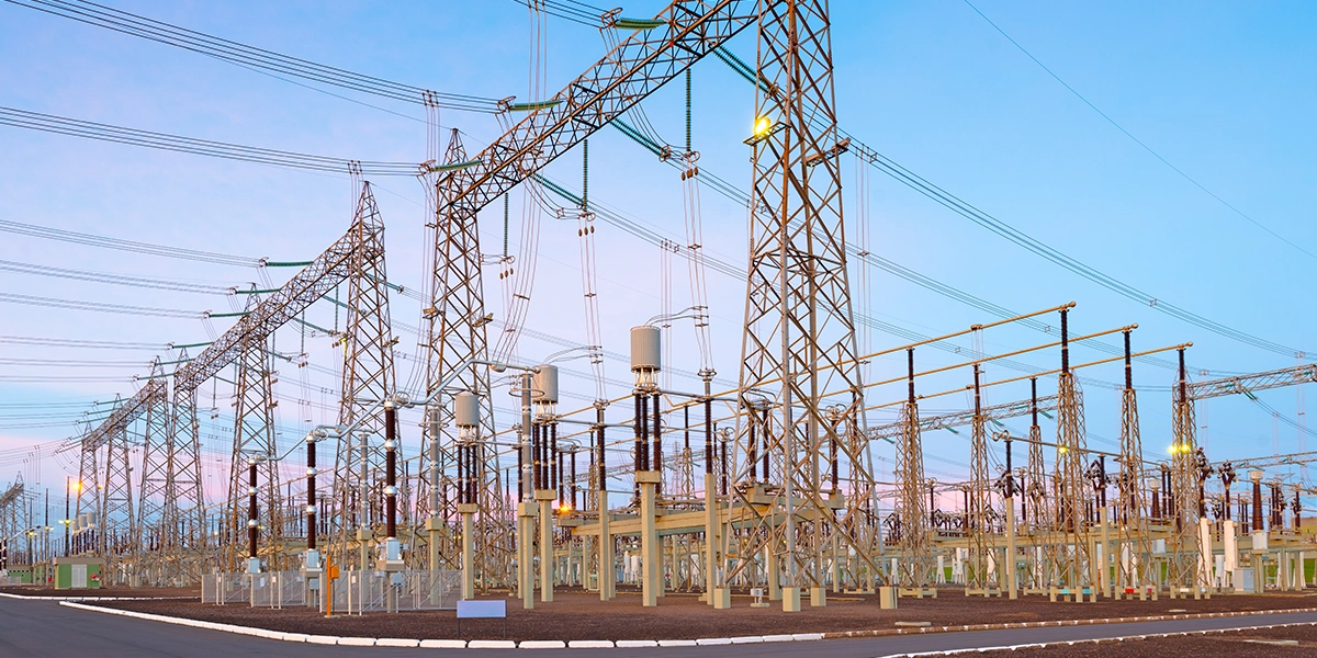
On a single-line diagram, a power-generation facility shows the generator and utility sources feeding a transformer, then an LV bus, then loads. In practice, that LV bus is implemented as a main distribution panel that feeds multiple feeder panels and local distribution boards across the plant.
A practical architecture looks like a clear hierarchy, summarized below.
Level
Equipment
Serves
Source
Generator step-down transformer / utility incomer
The plant
Level 1
Main distribution panel / LV switchboard
Major feeders and MCCs
Level 2
Feeder panels / industrial panels
Plant zones: turbine hall, boiler island, BOP, water treatment
Level 3
Local distribution boards
Loads: MCC rooms, control buildings, lighting, admin
All of these are power distribution panels, just at different levels. Optimizing your setup means deliberately coordinating this hierarchy rather than letting it evolve into a collection of unrelated boards.
What are you optimizing for?
In a power-gen facility, good distribution design balances three priorities. First, uptime and selectivity, so faults stay local and do not trip upstream panels. Second, safety and maintainability, so panels support safe operation with appropriate internal separation and clear access. Third, future flexibility, so the system can accept more generators, auxiliaries, or digital monitoring without a rebuild.
Low-voltage distribution systems are now expected to support energy efficiency, power quality, and reliability, not just carry current. If the main panel is undersized, if feeder panels are scattered without a zoning concept, or if boards are loaded arbitrarily, those three priorities start to conflict rather than reinforce each other.
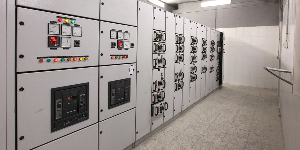
Main distribution panel: the plant's electrical anchor
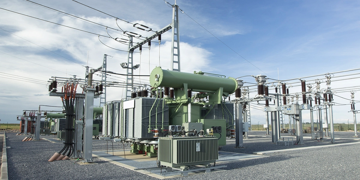
The main distribution panel, often implemented as an LV switchboard, is the electrical anchor of the facility. It receives power from the generator step-down transformer or utility incomer, then feeds major feeders to turbines, boilers, and balance-of-plant MCCs, sub-distribution feeder panels serving large zones, and sometimes direct large-motor loads.
Modern LV switchboards are described as the nerve center of industrial power distribution, because they centralize control, protection, and monitoring of multiple sources and loads. For a power-gen plant, this is where you decide how much fault energy the system can tolerate, how loads are structured, and how easily you can isolate, expand, or reconfigure.
Key design and rating decisions
When you specify or review a main distribution panel, a few decisions have outsized impact. The table summarizes what to verify and the governing standard.
Decision
What to verify
Standard
System voltage and grounding
Tested for nominal voltage (400/480/690 V) and grounding type
IEC 61439
Continuous current rating
Incomer and busbars sized with future margin
IEC 61439-1
Short-circuit withstand
kA rating exceeds prospective fault level at location
IEC 61439-1
Form of separation
Internal separation level for safe maintenance
IEC 61439-2
Ingress protection (IP)
Enclosure rating for the environment
IEC 60529
Confirm the panel is designed and tested for your nominal voltage and grounding (solidly grounded, impedance-grounded). Size the incomer and busbars not just for today's load but for plausible additions, like another generator on the same bus. Verify the short-circuit rating exceeds the calculated prospective fault level, since industrial LV panels are explicitly rated for fault withstand under IEC frameworks.
Higher forms of internal separation and appropriate IP ratings improve safety and enable selective maintenance without exposing live parts. IEC 61439 defines the general and product-specific requirements for low-voltage switchgear and controlgear assemblies, IEC 60947 governs the devices such as breakers, and IEC 60529 defines degrees of protection through the IP code. Many projects now add supplementary requirements such as shunt trips for remote tripping, clear external position indication, and front-operable breakers.
Practical optimization moves on the main board
Three moves use the main panel to optimize the wider setup. Standardize on a switchboard platform that can accept advanced metering, communication modules, and additional feeders later, even if you do not populate them immediately. Use electronic trip units on main breakers, with adjustable long-time, short-time, and instantaneous settings, to coordinate with downstream feeders and capture load data.
Finally, reserve physical and thermal space. Specify busbars and enclosures with documented spare capacity for additional feeder breakers or tie breakers, so future expansion does not require a complete replacement.
Feeder panels: localizing risk and complexity
Once power leaves the main panel, it flows into feeder panels or industrial panels that serve specific zones: turbine hall auxiliaries, boiler and flue-gas systems, cooling water and balance-of-plant, and common services like HVAC and lighting. These panels take the high-level capacity of the main board and break it into manageable chunks.
Their job is to keep faults and maintenance localized to a zone, so a problem in one area does not compromise the whole plant. Sub-distribution boards should be engineered with appropriate short-circuit ratings and device selection for their position in the system, not treated as generic boxes.
Feeder panel design considerations
Several parameters drive real-world behavior. The short-circuit rating at a feeder's location may be lower than at the main board but is still high enough to demand serious fault withstand from the panel and breakers. Undersizing the number of outgoing ways encourages temporary extensions and overcrowded panels, so allow room for additional circuits and clear cable management.
Panels in hot, dusty, corrosive, or outdoor locations need appropriate enclosure ratings and mechanical design. Grouping outgoing feeders by system, such as all boiler auxiliaries in one industrial panel, maps your electrical layout to the plant's process layout, simplifying operations and fault-finding.
Selectivity and coordination between main and feeder panels
From a protection standpoint, the main panel and feeder panels must be coordinated. For a fault within a feeder panel, its outgoing or incomer breaker should trip first. The main incomer should only trip for failures in its own bus, or as backup for extreme faults.
Engineering practice emphasizes plotting time-current curves for upstream and downstream devices and choosing settings that preserve selectivity. Poorly matched components, for example a fast-acting main breaker feeding slower downstream MCCBs, can make the main panel see every local fault and trip first. A simple optimization is to standardize a family of molded-case or air circuit breakers with compatible trip units across the main and feeder levels, so coordination is predictable and supported by manufacturer data.
Distribution boards: optimizing auxiliary and control circuits
At the edge of the hierarchy are distribution boards that supply final auxiliary and control circuits: local control power for MCCs and process skids, control rooms and PLC/DCS cabinets, and critical small-power and lighting. In a power-generation context, these boards are the final step delivering power into the control and balance-of-plant systems that keep units online.
Although they carry smaller currents than main and feeder panels, their design strongly influences whether nuisance tripping interrupts critical auxiliaries, how quickly engineers can isolate and restore faulty circuits, and the safety of routine isolation on a live plant.
Layout and component choices that matter
For a distribution board, layout is a design decision, not just a wiring detail. Group ways by process or equipment package, such as all condensate-system auxiliaries together, so protection, isolation, and future expansion are easier to plan. Select breaker characteristics and any residual-current protection (RCDs) based on load type, fault levels, and upstream coordination, rather than a one-size-fits-all device list.
Ensure the board includes clear incoming and section isolation points that support your plant's lockout-tagout and maintenance strategy without taking down unrelated systems. Framing these as part of the specification keeps the final level of your hierarchy aligned with the same engineering logic as your main and feeder panels.
Electrical panel components that drive performance
Inside every panel are components whose selection directly impacts uptime, safety, and efficiency. The table maps each to its role and key specification.
Component
Role
Key specification
Incoming/outgoing breakers (ACB, MCCB)
Primary protection
Interrupting capacity > fault level; trip unit type
ACBs are usually selected for main incomers, bus couplers, and high-current feeders, MCCBs are versatile feeder and motor-protection devices, and under IEC 61439 temperature-rise verification is a formal part of assembly compliance, which is why busbar selection is part of assembly verification rather than a standalone conductor calculation.
Electronic trip units with adjustable settings support selective coordination, load recording, and remote monitoring. Multi-function meters and communication gateways link the panel into plant SCADA or energy-management systems, letting operators optimize load distribution and troubleshoot faster. SPDs at main and feeder panels clamp transient overvoltage from switching, faults, or lightning, while harmonic filters and power-factor-correction banks improve efficiency where appropriate. Interlocks, clear position indication, compartmentalization, and front access let many routine tasks be done without exposing live parts.
Turning panels into an optimization strategy
Many power generation sites have grown over decades. Every project or retrofit added another industrial panel, another distribution board, another small switchboard. Over time, this creates a patchwork of different ratings, manufacturers, and philosophies.
Industry analysis indicates global demand is shifting toward more standardized, modular, and smart panel platforms, because they are easier to engineer, operate, and expand. Moving toward a coherent set of panels built on consistent design rules lets you apply one coordination philosophy across the plant, simplify spares and training, and implement monitoring in a repeatable way across units or sites.
Practical steps for engineers and buyers
When planning a new project or major upgrade, follow this workflow:
Map your current hierarchy. Identify every main panel, feeder panel, and distribution board in the system.
Check ratings and fault levels at each panel against the calculated short-circuit duties.
Flag weak points: panels that are under-rated, impossible to maintain safely, or known coordination trouble spots.
Build a specification for replacements based on IEC 61439 compliance, adequate short-circuit and thermal ratings, clear internal separation, compatible breaker families, and provision for metering and communications.
Source and standardize across your fleet through a platform that lets you compare and procure consistent panels.
Frequently asked questions
What is a power distribution panel?
A power distribution panel is an enclosed assembly that receives incoming electrical power and divides it into protected outgoing circuits. In industrial plants, panels form a hierarchy of a main distribution panel (LV switchboard), feeder panels, and local distribution boards, each built to IEC 61439.
What is the difference between a switchboard and a panelboard?
A panelboard handles branch circuits up to about 1,200 A at 600 V (UL 67) and is wall-mounted with front access only. A switchboard handles up to about 6,000 A (UL 891), is floor-mounted, and distributes power to feeders and large loads. Switchboards serve as main and feeder distribution; panelboards serve final circuits.
What is the difference between a switchboard and switchgear?
Switchgear (UL 1558) uses compartmentalized, draw-out breakers and withstands a short circuit for up to 30 cycles, versus 3 cycles for switchboards and panelboards. It is used in mission-critical environments like data centers and power plants where maintenance without shutdown and high withstand ratings are essential.
What is IEC 61439?
IEC 61439 is the international standard for low-voltage switchgear and controlgear assemblies. It defines how panels are designed, verified, and tested, including temperature rise, short-circuit withstand, and form of separation. Part 1 covers general rules; Part 2 covers power switchgear and controlgear assemblies.
What is a form of separation in a panel?
Form of separation defines the internal barriers between busbars, functional units, and terminals, from Form 1 (no separation) to Form 4 (full separation of busbars, devices, and terminals). Higher forms allow safer maintenance of one section while others stay live.
How do I coordinate main and feeder panel protection?
Plot time-current curves for upstream and downstream devices and choose breaker settings so the device closest to a fault trips first. Standardizing compatible breaker families with electronic trip units across the main and feeder levels makes this selectivity predictable.
Source power distribution panels through eINDUSTRIFY
eINDUSTRIFY is a premier global B2B marketplace for industrial supplies, connecting plant, engineering, and procurement teams with vetted suppliers of power distribution panels and components. Every seller is vetted, so you source genuine, IEC 61439-compliant assemblies, not gray-market stock, with the ability to compare ratings and configurations in one place.
When you reach the sourcing step, browse the Electrical and Industrial Control categories for main distribution panels, feeder panels, and distribution boards, along with related Power Transmission components. These panels serve the Power Generation and Data Centers sectors directly. For multi-site standardization or full project sourcing,submit an RFQ and our team will match you to the right suppliers with fast price comparison. Call 1-888-774-7632 or email info@eindustrify.com to get started.
Tags: power distribution panels LV switchboard feeder panels IEC 61439 distribution board electrical panel components